In the spring 2025 edition, I examined the failure modes observed at NBBI’s Pressure Relief Laboratory (PRL), as well as some possible causes for these failures. Two possible causes for many different failure modes were insufficient test stand volume and poor adjustment ring settings. To expand upon this, I will take a closer look at both issues by devoting an article to each. This article will discuss the effects of low-volume test stand on valve setting, specifically with regard to obtaining accurate measurements for popping pressure and blowdown.
Need for Sufficient Accumulation Volume
The purpose of testing and setting pressure relief devices in the shop is to replicate, as closely as possible, service conditions and ensure that the devices will operate correctly in service. If the test stand can’t replicate service conditions in any meaningful way, the test results can’t be reliable. Even worse, they may lead to adjustments that cause a valve to fail to perform properly when placed into service.
As the valve installed on the test stand starts to relieve pressure, the rate at which the pressure inside the test stand drops will depend on the valve size and the test stand's size. The larger the valve, the faster it can relieve the pressure. The larger the vessel, the more volume there is to relieve, so the pressure will drop more slowly. If this relationship between the valve size and the test stand volume is too lopsided, it will not even be possible to observe the valve’s true opening and closing characteristics.
For most valves certified for use on compressible fluids, the set pressure definition used by the manufacturer is “pop.” This refers to the pressure at which the valve exhibits rapid opening, from either no discharge or a slight leak to full opening. For a valve with this set pressure definition, it is critical to achieve this behavior on the test bench to properly set the valve. If the test stand volume is too low to pop the valve, it is not possible to recreate the service condition or establish the manufacturer’s defined set pressure. This can lead to a valve going into service without being properly set or adjusted for the conditions.
NBIC Part 4, Supplement 5
The National Board Inspection Code (NBIC) requires each repaired valve to be tested for set pressure as defined by the valve manufacturer and listed in NB-18, seat tightness, and blowdown when required by the original code of construction. To ensure that the data obtained from these tests is accurate, NBIC Part 4 4.6.1 b) 1) mandates that the test equipment used in repairs must include a pressure vessel of adequate volume and pressure source capacity. The question, then, is how to determine what test vessel volume is sufficient.
Fortunately, NBIC Part 4, Supplement 5, provides guidance and recommendations on the appropriate size of test vessels for compressible fluid testing based on the size of valves to be tested. In addition to sample test stand schematics and descriptions, the supplement includes charts for determining test vessel volume for systems using steam or air. The charts show the relationship between test vessel volume, valve flow area, and required blowdown measurements.
Another consideration is the rate at which the test stand can be supplied with pressure from the source. This will be determined by the source pressure and the size of the line supplying pressure to the test stand. If the line supplying pressure to the vessel is too small or the source pressure is too low, the capabilities of the test system will be limited. Some assumptions are made regarding the pressure source's supply capabilities, as stated in Supplement 5. If the ratio of the valve’s flow area to the volume of the test vessel is small enough, the impact of the supply line size becomes less of a factor.
Liquid Applications
While the NBIC supplement mentioned above gives guidance for test stand volume for compressible fluids, having sufficient test stand volume and source pressure are also critical for testing valves for incompressible fluids. Many liquid test stands are constructed utilizing a J-tube or dip-tube design.
In both cases, pressure is supplied by using compressed gas or air to pressurize the gas space over the liquid and create a piston effect. These designs, coupled with common set pressure definitions for liquid service valves, can make test stands that are too small to fully test many liquid valves appear to be completely sufficient.
As mentioned in previous articles, the set pressure for liquid service valves is often defined as the “first steady stream,” in which the liquid discharged from the valve forms a vertical stream about as thick as a pencil. Since this set pressure definition requires the valve to relieve such a small volume, it is possible to accurately measure set pressure even on a small-volume test stand.
The issue comes in verifying that a liquid valve will fully open within the code-specified overpressure. For a liquid valve to relieve its full rated capacity, it must continue to open until it reaches a full lift “pop” or “gush.” On a small-volume test stand, it can be impossible to measure or even achieve full lift gush accurately. Even if a valve’s “first steady stream” set pressure is set perfectly, if the valve does not fully open within the required overpressure, it can still lead to an unchecked overpressure condition in service. In fact, this failure to fully open within tolerance is one of the most common failure modes observed on liquid service valves tested at PRL.
Effects on Blowdown Measurements
So far, the effects of test stand volume have been discussed with regard to set pressure and relieving capacity, but another important point to consider is the effect of insufficient volume on blowdown measurements.
In the context of pressure relief device testing, blowdown is the term used to describe the difference between a valve’s opening and reclosing pressure. As discussed in my previous article covering ring settings in the summer 2025 edition, proper setting of a valve’s adjusting rings is crucial to ensuring that a valve functions as intended. This includes the correct blowdown. ASME Section I mandates that “V” stamped steam valves have a minimum 2% blowdown, which is necessary to ensure the valve reaches its full rated lift and capacity and operates without chatter. Many “UV” designated valves are also designed to operate with a blowdown between 5-10%.
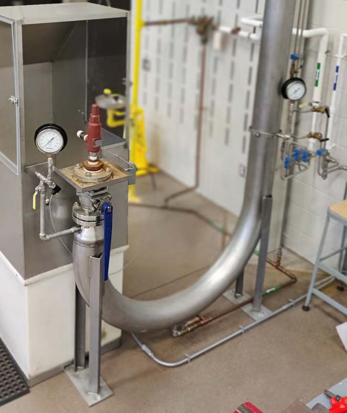
This is a J-tube test stand for liquid service valves
at the National Board's Inspection Training Center.
Obviously, to make meaningful adjustments to blowdown, the test stand must have sufficient volume to allow accurate reclosing pressure readings. If the test stand volume is too small, the blowdown readings will be artificially long. This can lead to problems with short blowdown, inducing chatter in the valve during an overpressure incident. Valve manufacturers have recommendations for adjusting ring settings. Still, if a specific blowdown value is required and the test stand is not large enough to accurately measure blowdown, it can be impossible to verify that the blowdown requirements have been met.
Ultimately, the overarching goal of valve testing is to ensure the safe operation of the equipment the valve will protect, not just to pass laboratory testing. Pressurized equipment contains a massive amount of stored energy, and pressure relief devices are the last line of defense in protecting against the catastrophic release of that stored energy.
With that in mind, it is of the utmost importance that the equipment used to test these devices, from measurement instruments to the test vessel itself, be capable of providing meaningful information about their performance.