An inspector stands in front of an air receiver during a routine inservice inspection. The nameplate, in this case, lists head and shell thickness. A UT reading comes back below it, or close to it, or above it – and now a decision has to be made.
That single measurement can trigger a series of questions that are not always easy to answer.
Can the inspector verify that number independently? Do they have access to the original data report? Do they have the applicable code book – and the correct edition – for a vessel that may have been built decades ago? Do they know where to find the material stress values that governed construction at the time, or should they simply trust whatever is stamped on the nameplate? Do they know whether the designer added extra thickness for loadings or, for example, whether anti-vibration measures are required and specifically what the manufacturer recommends? Were the loadings of a compressor installed on top of the vessel considered, and was there a limitation on the compressor related to horsepower or weight or to something else?
These are not rhetorical questions. They are the day-to-day reality of field inspection, and the honest answer, for a large share of vessels in service, is that nobody has really worked it out.
Fifty Years of Diagnosis
This problem is not a new discovery. It has been diagnosed, in nearly identical terms, at least three times in the history of The National Board of Boiler and Pressure Vessel Inspectors (NBBI), without ever producing a durable fix.
The first line drawn specifically around commodity air tanks came from California in 1928, when the state’s chief boiler inspector told industry participants during the Sixth General Meeting about the multi-year fight to bring air pressure tanks under enforceable safety orders. The resulting rules required shell thickness to be stamped on the tank nameplate and the heads to carry small test holes with brass plugs, specifically so head thickness could be checked for corrosion loss over the vessel’s life – an early, physical ancestor of comparing a UT reading against a nameplate value.
The sharpest version of the diagnosis, though, is in the April 1971 edition of the BULLETIN. That issue compiled four jurisdictional reports on air receiver failures, and one of them described a compressor-mounting failure investigated after a valve began sticking and the resulting vibration fatigued the welds attaching legs and a bed plate to the tank top. The report noted, almost in passing, that “the vessel manufacturer indicated that the supports were to be installed by an outside agency.” That is not a paraphrase. It is the same disclaimer, in substance, found on air receiver data reports built decades later – in the remarks section where a short sentence assigns responsibility for anti-vibration protection to the user and is silent on which, if any, loadings were considered in calculating required thickness. NBBI was already citing that exact disconnect as a documented cause of catastrophic failure 55 years ago.
Six years later, in January 1977, NBBI produced the document titled NB-45, A Review of Air Receiver Casualties Where the Compressor has been Mounted on the Receiver, which gave the same finding scale and documentation: California alone reported over 200 cracked or ruptured air tanks across six years in the 1970s, with NBBI’s own account acknowledging the true number was likely higher, since many failures went unreported. Arizona responded by prohibiting compressor mounting on tanks not specifically engineered for it. California reiterated the requirement to document head and shell thickness on the nameplate itself, so that a field inspector could compare a UT reading to a stated baseline without the full data report in hand, but without ever defining, in any binding way, what that stamped number represented or how it gets there. California’s additional nameplate stamping requirements never became a standard practice and are not currently required to meet the ASME Section VIII code. The advantage of including it there would be stronger conformity assessment of its meaning, Authorized Inspector oversight on its inclusion and accuracy, and making it available to all jurisdictions.
What connects 1928, 1971, and 1978 is not really about thickness. It is a mismatch between how a vessel was designed and how it was used in service, with no mechanism along the way to catch the divergence. And, as the 1971 reports already show, NBBI named that exact mechanism in its own pages before most of the vessels currently in service were even built.
The Missing User
ASME Section VIII, U-2(a), places a specific obligation on “the user or his designated agent” to establish the design requirements for a pressure vessel – the loadings from UG-22, the need for corrosion allowance, the service conditions the vessel will actually see. Two of UG-22’s own enumerated loadings describe the classic air-receiver hazard almost exactly: paragraph (c) calls for considering “superimposed static reactions from weight of attached equipment, such as motors, machinery,” and paragraph (e) calls for considering “cyclic and dynamic reactions… from equipment mounted on a vessel.” The code has had the right categories in place for decades. What it has never solved is who, for a commodity vessel, is actually positioned to tell the designer that a particular loading applies and, if done, the manufacturer’s data reports currently lack the capacity to capture it in a meaningful way to communicate that information to the user and inspector.
The U-2(a) framework assumes a user capable of the analysis: an owner with engineering judgment, or an agent acting on their behalf, feeding real operating conditions back to the manufacturer before the vessel is built. Air receivers routinely break that assumption. A shop owner buying a receiver from a distributor, a big-box retailer, or an industrial supplier is not exercising – and is not equipped to exercise – the U-2(a) function. A recent field example from California’s Pressure Vessel Unit shows how quietly the resulting gap – a midstream assembler increasing a loading without checking with the designer – can open. A manufacturer of standard 80-gallon vertical air receivers had traditionally paired the tank with a 5-horsepower compressor motor; at some point, the same model line began shipping with a 7.5 HP motor to gain a few more cfm, with nothing on the tank’s own nameplate reflecting the change. A field inspector could only catch it by reading the motor nameplate directly or, with enough experience, noticing the drive pulley had grown large enough to nearly touch the compressor pulley. That the extra 2.5 HP mattered was only learned by a failure in the field. That is UG-22(c) and (e) in miniature – a superimposed, cyclic loading added to an already-assembled product line, with no design review triggered anywhere along the way.
This reframes the original question. Even if an inspector could perfectly recalculate minimum thickness from the applicable code formula, the harder problem is knowing what to check it against. If the actual loadings present in the field were never contemplated by the designer, thickness compliance alone doesn’t tell the inspector whether the vessel is fit for its actual service.
The Case Study: National Board 47490
I was working with the state of Washington Chief Inspector Mike Carlson and his supervisory staff to learn how they approach inspection of the three-foot diameter and less air receivers in the state. UT is permitted as an alternative to internal inspections for these items. Further, they were able to provide several nameplate images cross-referenced to air receivers installed and inspected in the state. I suspect their proximity to California explained why the thickness readings were present on air receivers being installed in the state, as their state rules and regulations had no requirement for them.
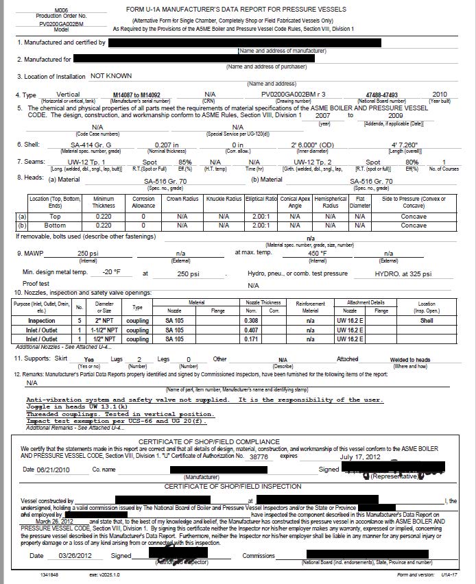
Data report for case study 47490
A 2010 ASME stamped air receiver, NBBI No. 47490, illustrates the problem concretely. Manufactured for the medical equipment industry and stamped for a 250 psi MAWP vessel, its data report lists a shell built from SA-414 Grade G at 0.207 in. nominal thickness and elliptical heads in SA-516 Grade 70 at 0.220 in., with no corrosion allowance. The data report notes that an anti-vibration system was not supplied – “it is the responsibility of the user” – the same disclaimer the BULLETIN had already flagged as a documented failure cause.
Recalculating the required thickness using UG-27, without relying on the nameplate, gives a shell thickness identical to the nameplate value. Interestingly, the minimum head thickness on the data report stated 0.220 while the nameplate was stamped “HD 0.216.”
The acceptance criteria make the issue more complex. Washington applies the NBIC UT criteria, which allow up to a 25% thickness loss from the “required wall thickness.” However, the National Board Inspection Code (NBIC) does not currently define that term. ASME Section VIII paragraph UG-16 also sets a separate minimum thickness of about 0.094 of an inch for materials used in compressed-air service. That minimum is separate from both the vessel’s design thickness and the NBIC percentage-based limit. Further, ASME Section VIII paragraph UG-25(e) permits telltale holes for this service and requires them to have a depth not to be less than 80%, which means leakage would occur when 20% of the required thickness has been breached.
None of this means the vessel in the example above is unsafe. It means an inspector confronted with this vessel has no single, authoritative reference thickness to check a UT reading against – only a recalculated number, a nominal number for the shell on the data report, and maybe a number stamped on the nameplate that we have no idea how it got there, and different philosophies for when a vessel comes out of service or possibly is derated.
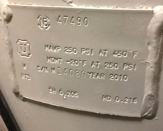
Nameplate for case study 47490
California offers a third philosophy worth describing on its own terms. Its field protocol, documented in DOSH Circular Letter PV-2017-1, works differently again: a 10% reduction from nameplate thickness as the first check, a fallback recalculation using either the actual data report or a standardized set of default material values when no data report survives. The document contains detailed instructions, a flow chart, and a full page of examples that describe their evaluation criteria.
The Recommendation
Three things need to happen, and input and buy-in from the ASME Section VIII committee, the NBIC committees, and our industry partners such as the PVMA are critical to improving this confusing situation.
First, the industry needs consistent thickness terminology carried through the vessel’s entire lifecycle. Design thickness, required thickness, and nominal thickness are already distinct terms in ASME Section VIII Mandatory Appendix 3, but they are not all applied uniformly or even appear on data reports.
Second, required thicknesses for shells and heads should be included as part of the ASME nameplate. This will provide conformity assessment as to the accuracy and validity of these values. An inspector should not and cannot reverse-engineer the vessel and speculate what the designer had and had not considered.
Third, the industry needs a mechanism for capturing the loadings considered by the designer for a given pressure vessel on the manufacturer's data report. A clear signal to inspectors that an air receiver has or has not been designed for compressed air service and, if so, what loadings were considered such that cyclic loadings were considered by using thicker shell and head material, requiring anti-vibration isolation (what that includes), or prohibiting the compressor from being mounted directly on the tank.
The most important thing to do right now is to communicate and collaborate. Many of these simple air receivers are captured on U-1As, which is a short version of the U-1 report. The U-1A was meant to be a simple short form printed on one side so it wouldn’t have to be removed and reinserted in the typewriter. We are beyond typewriters and paper.
NBBI’s JRS Register is in development, which will capture the data fields for all the registered data report forms electronically. JRS Inspect, which manages the post-construction life cycle of many of these vessels, will be seeded by and have access to the data report information, putting it in the hands of the inspector in the field. Accurate and actionable information on the important design, material, and construction characteristics is what is needed to flow from the manufacturer to the user, inspector, and repair organizations.
The question is: Are all the fields currently on the data report forms needed and what needs to be added? We need your help answering these questions.
Until these shortcomings are addressed, the answer to the original question is uncomfortable but honest: Inspectors are being asked to verify a number whose meaning shifts depending on the document in front of them and the jurisdiction they’re standing in, for a class of vessels whose real-world service may not match how it was designed for in the first place – a problem NBBI’s contributors were already describing in exact terms in 1971.