 Acoustic Emission Examination of Metal Pressure Vessels
Print Date: 7/5/2025 12:22:08 PM
Dennis A. White
President of Measurement Services International, Inc.
Member ASNT, ASTM, ASM, TAPPI, AWEG, and ASME Subcommittee V
Chairman for the Special Working Group on Acoustic Emission
57th General Meeting
May 1988
Category: Design/Fabrication
Summary: The following article is a part of National Board Classic Series and it was published in the National Board BULLETIN. (6 printed pages)
Acoustic emission (AE) is a meticulous nondestructive examination (NDE) method that exposes deficient areas in pressure vessel integrity. It is the only NDE method capable of assessing volumetric integrity during a vessel pressure test period. When AE is used as a primary examination method during hydrostatic testing, it supports all other NDE methods.
The guidelines, standards, practices, glossaries, and codes for AE are available from national organizations such as the American Society for Testing Materials (ASTM), the American Society for Nondestructive Testing (ASNT), and the American Society of Mechanical Engineers (ASME).
In 1985, a code case was approved by Section VIII to allow the use of acoustic emission in lieu of radiography on pulsation dampeners. Acoustic emission examinations Article 11 for fiber reinforced plastic vessels (Section X) was issued in June 1985. In December 1988, there will be the publication of Article 12, "Acoustic Emission Examination of Metal Pressure Vessels" (Section VIII).
Acoustic emission nondestructive methods are numbered as Examination Articles 11 & 12 in Section V of the ASME Boiler and Pressure Vessel Code . These articles provide the method for detecting and mapping deficiencies in vessel integrity during hydrostatic testing.
A Simple Concept
Slamming a door creates an audible burst of sound (an event). The event can be described as the rapid release of energy from a localized area. The event caused by slamming a door produces a pressure wave that travels through the air. This pressure wave could hit a wall and bounce around a room as an echo. The packet will hit the eardrum of a person standing near the door. The strength of the burst of noise hitting the ears will depend on the proximity of the person near the door. The ears allow detecting of the number of events (number of times a door slams) and the "strength" of each event. The same event activity occurs in solid materials, but above the range of human hearing.
Metals deform in localized areas. Examples of small deformation could be a plastic zone, or metal embrittlement. Large visual examples of deformation can be erosion pitting and cracks. These deformations may be generated during vessel manufacture or operation. Many "events" can be generated from each area of metal deformation. Each one of these events creates a stress wave that travels through the metal. If there is no metal deformation, there will be no event activity. Special sensors are needed to detect acoustic emission events caused by metal deformation.
Acoustic emission sensors are extremely sensitive to the high frequency burst events that occur as a result of material deformation. They react much the same way the ears do. AE sensors provide an electrical output response proportional to the strength of each event they sense. Their output can be seen as an electrical burst sinusoidal characteristics.
Acoustic emission sensors properly placed at interval, to cover an examination area, would sense the events from areas deforming as a result of an applied stress (i.e., hydrostatic test). More than one sensor could be hit by the stress wave from a single event. The order of event detection can be used to locate the area originating the event activity.
Using the AE event location information as a map, other NDE methods can be used to further examine the areas of vessel deformation. Acoustic emission supports other NDE methods, making their use more efficient and cost effective.
Statistical Data
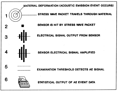
A defective area in a vessel causes an event to occur. An event results in a stress wave packet traveling through the metal and hitting acoustic emission sensors. Each AE sensor hit creates an electrical output. The electrical output is amplified and transmitted through a cable to a signal processor. The combination of sensor preamplifier and cable are referred to as a channel. The signal processor monitors its input from each channel with an adjustable electronic threshold (examination threshold). When the electrical signal from the channel crosses this examination threshold, the event is detected. Several parameters can be measured from this detected event signal. (Figure 1)
FIGURE 1

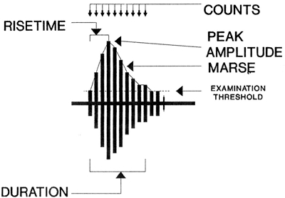
The parameters measured (Figure 2) from a detected event signal include counts, rise time, amplitude, duration, and the measured area under the rectified signal e nvelope (MARSE - previously known as relative energy). For each monitored channel, the AE system can also provide a parametric voltage (pressure, temperature, level, etc.), and a sensor specific arrival time and location zone for each detected event.
FIGURE 2

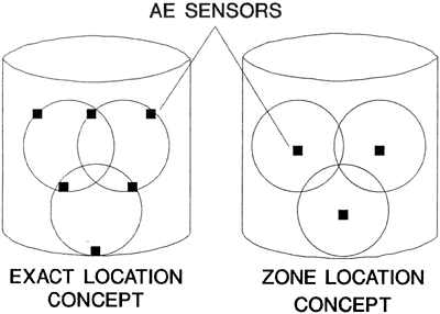
AE data is presented in formats that allow the examiner to determine the origin(s) of events. Location data is of two basic types: zone and exact source (Figure 3). Definitions for each of these and other AE items are found in SE610, Section V of the ASME Boiler and Pressure Vessel Code .
FIGURE 3

What is Required by ASME Section V, Article 12?
- What are specifications for AE equipment and personnel?
The AE system will measure sensor hits on each channel and parametric voltage. For each electrical response to a sensor hit (crossing the examination threshold), the system will measure counts, peak amplitude, arrival time, and MARSE.
Personnel qualification and certification is specified by the referencing code section.
- Primary calibration
The AE instrument must be calibrated annually to a recognized national standard. Whenever the AE instrument fails to meet the requirements of an on-site calibration, it should receive a primary calibration. The equipment specifications for this calibration are provided by the manufacturer.
- On-site calibration
Before and after each vessel test, or series of tests, the examining channel inputs to the AE signal processor (main processor) must be checked with an electronic waveform generator. This requirement will prevent reporting of unsatisfactory data. The AE system output tolerances for this requirement are specified in Appendix I of Article 12.
- System Performance Check
After the sensors are mounted on the vessel (before testing) and before they are removed from the vessel (after testing), each channel of the system will be checked. The response of each channel to a simulated event (pencil lead break, etc.) from a fixed distance on the vessel is tabulated. The measured event signal strength for each channel must be within a fixed value of the average of all the channels. This value is specified in the "Systems Performance Check" section of Article 12.
- Simulated event
An event may be simulated on the vessel surface to check system/channel performance or to determine sensor spacing. The simplest method of creating a reproducible event is by using a lead break. Specific requirements are that it be a .3mm2H lead, extended from a mechanical pencil .1 inch. The lead will be broken at an angle of 30o to the examination surface. No part of the pencil (only the lead) should touch the vessel during or after the break.
The breaking of the lead creates a reproducible stress wave packet traveling through the metal, which can be sensed by the AE sensor.
- Procedure
Each AE examination will be done according to a procedure. The minimum requirements for a procedure are specified under the title of "Written Procedure Requirements" in Article 12. These requirements encompass the examination material, object, instrument/components, parameters, recording, and personnel.
- Sensor spacing to locate an event
All data detected from any AE system channel used in the examination is pertinent to the evaluation criteria. There must be assurance that each part of the vessel under test is being monitored by an AE sensor. To do this, sensor spacing can be determined on the vessel according to the mandate of "Sensor Spacing" in Article 2. This involves creating a simulated event at point(s) away from the sensor(s) mounted on the vessel. The location method used during examination to determine event origin dictates sensor spacing requirements.
- Vessel testing and examination
The hydrostatic test performed during vessel acceptance testing is one of the best times for an AE examination. The vessel stressing sequence and the extent of examination are specified by the referencing code section. An example of a vessel stressing sequence and sensor placement guidelines for a variety of vessels is provided in Article 12.
The AE examination process is sensitive to environmental conditions (rain, blow dusting, etc.), motors and rubbing cables, piping, and mechanical noises from adjacent pumps. No examination should be run when sensor noise is too high.
Most AE parameters will exhibit a linear relationship to increasing load. During the examination process there could be a condition where the rate of the acquired data from counts or MARSE departs from linear. When this occurs, caution is advised. This caution is covered under "Test Termination" requirements. The sensor area originating the high data rate should be safely investigated to determine probable cause. The test may be resumed when appropriate corrective action has been taken.
- Reporting Examination Data
The report of the examination must include those requirements in "Documentation." The records that must be retained with the vessel are specified in "Records."
- Evaluation Criteria
The examination criteria threshold is the adjustable electronic threshold for detecting event signals from an AE channel. The evaluation threshold will be at or above the examination threshold. The value of the evaluation threshold will be specified by the referencing code section. An example of a format for evaluation criteria is provided in Article 12.
The evaluation criteria considers two vessel conditions: one condition having seen no pressure, the other having seen previous pressure. These considerations are important due to the fact that there will be an absence of detectable events at a fixed examination threshold prior to reaching previously applied pressures (Kaiser effect). The antithesis (Felicity effect) indicates a deforming area in the vessel.
Personnel Training
Acoustic emission qualification and certification requirements are found in the 1984 edition of SNT-TC-1A. Schools and seminars about the uses of AE technology are offered by consultants and manufacturers of AE equipment.
Two Areas
Almost every pressure vessel can be successfully examined with AE. Evaluation criteria is needed in order to satisfy code requirements. To begin with, two areas for AE evaluation criteria should be: (1) large vessels requiring field erection and (2) vessels made of materials subject to weld induced cracking or embrittlement.
Final Thoughts
- Acoustic emission technology is an excellent supporting technology for other nondestructive testing methods.
- AE is regularly used for vessel inspection by companies in the chemical and petrochemical industries. These companies have provided the support for both ASME acoustic emission documents.
- The Department of Transportation has acknowledged preapproved inservice examination using AE to be superior to previously used methods of hydrostatic testing.
- The application of the technology to pressure vessels has been standardized for over 10 years by ASTM.
- Acoustic emission applications range from continuous in-service monitoring of processes to new product examinations lasting one second.
Editor's note: Some ASME Boiler and Pressure Vessel Code requirements may have changed because of advances in material technology and/or actual experience. The reader is cautioned to refer to the latest edition of the ASME Boiler and Pressure Vessel Code for current requirements.