 Environmental Heat Exchangers
Print Date: 10/23/2024 8:32:08 PM
Environmental Heat Exchangers
Print Date: 10/23/2024 8:32:08 PM
Francis Brown
National Board Staff Engineer
Winter 1996
Category: Operations
Summary: The following article is a part of National Board Classic Series and it was published in the National Board BULLETIN. (4 printed pages)
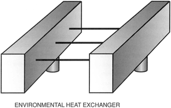
An environmental heat exchanger, as defined by the ASME Code, is a single-chamber pressure vessel that exchanges energy with the surrounding atmosphere. The heat exchanger consists of one or two headers and a number of tubes separating the working fluid from the atmosphere. The tubes may or may not be finned. The heat exchanger is a single-chamber vessel because none of the components is designed to be operated independently of the other components. A typical heat exchanger is shown in Figure 1.
FIGURE 1
Presently, a number of methods are used to complete the Manufacturers' Data Reports (MDRs) for environmental heat exchangers. Some heat exchangers are documented on U-1A data report forms and some are documented on U-1 report forms. The information included in the data report varies from manufacturer to manufacturer. Often, data reports must be returned for revision because of insufficient information.
Therefore, the National Board is offering the following guidelines to assist manufacturers with the completion of the data reports for this type of heat exchanger. Either the U-1 or the U-1A report form may be used for documentation of a single-chamber vessel, but it may be easier to complete the U-1 form for this type of heat exchanger. The U-1 form is used in the following example.
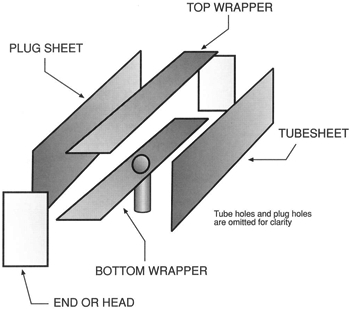
For this example, the headers are rectangular in cross section, are designed to the requirements of Appendix 13, and the opposite walls have the same thickness. An exploded view of a header is shown in Figure 2.
FIGURE 2
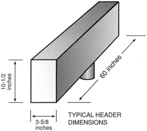
Typical header dimensions are shown in Figure 3.
FIGURE 3
The majority of the items on the U-1 form are completed in the normal manner. Only those items affected by the heat-exchanger configuration are discussed below.
- The vessel is identified in Item 4 of a U-1 data report form as a heat exchanger.
- The headers are described as shells in Item 6, as shown in Table 1. "Headers" is entered under "Shell" to indicate that the components described in Item 6 are not standard shell courses.
- The significant cross-sectional dimensions (inside) of the headers are listed for the vessel diameter, as shown in Table 1. The remaining part of Item 6 is completed as needed. The longitudinal and circumferential joint efficiencies are determined from 13-4, 13-5, UW-12, and UG-23(c). In this example, corner welds were used to fabricate the headers.
- The ends in the headers are documented as flat heads, as shown in Table 2. The asterisk indicates that the significant head dimensions are shown in "Remarks."
- Items 9, 10, and 11 are completed in the normal fashion.
- Item 12 is not completed because this vessel is not a tube-in-shell heat exchanger, and the part was described in Item 6.
- The tubes connecting the headers are described in Item 13.
- All penetrations in the headers are described in Item 19. The threaded openings in the "plug sheet" are treated as nozzles.
- The head dimensions and the length of the tubes are added to "Remarks" (see below) to complete the description of the heat exchanger.
TABLE 1
| 6. Shell (a) No. of Course(s): 1 each |
(b) Overall length (ft. & in.): 5 ft. 0 in. |
| Course(s) |
MATERIAL |
THICKNESS |
| No. |
Diameter, in. |
Length (ft. & in.) |
Spec/Grade or Type |
Nom. |
Corr. |
| 1 |
3-5/8 x 10-1/2 |
5 ft. 0 in. |
SA-516 GR 70 |
See Remarks |
| 1 |
3-5/8 x 10-1/2 |
5 ft. 0 in. |
SA-516 GR 70 |
See Remarks |
TABLE 2
| 7. Heads: (a) |
|
SA-516 Gr70, NONE |
|
(b) |
|
SA-516 Gr70, NONE |
|
|
| (Mat'l Spec. No., Grade or Type) H.T. Time & Temp. |
(Mat'l Spec. No., Grade or Type) H.T. Time & Temp. |
|
Location
(Top, Bottom, Ends) |
Thickness |
Radius |
Ellip-
tical
Ratio |
Conical
Apex Angle |
Hemi-
spherical Radius |
Flat
Dia-
meter |
Side to Pressure |
Category A |
| Min. |
Corr. |
Crown |
Knuckle |
Convex |
Concave |
Type |
Full,Spot,
None |
Eff. |
| (a) |
ENDS |
0.625 |
|
|
|
|
|
|
* |
|
|
S |
NONE |
1 |
| (b) |
ENDS |
0.625 |
|
|
|
|
|
|
* |
|
|
S |
NONE |
1 |
22. Remarks: Item 6: Tubesheet and plug sheet thickness: 1.25 in.; top and bottom wrapper thickness: 1.00 in.
* Item 7 - Head dims.: 3-5/8 x 10-1/2 in.
Item 13 - Tube length: 20 ft.
Editor's note: Some ASME Boiler and Pressure Vessel Code requirements may have changed because of advances in material technology and/or actual experience. The reader is cautioned to refer to the latest edition of the ASME Boiler and Pressure Vessel Code for current requirements.