Every inspector should be able to determine the allowable pressure for a cylindrical component of a boiler or pressure vessel.
Calculating the allowable pressure on boiler tubes, drums, shells, or headers is an example of making this determination. For a boiler component under internal pressure, the calculation is quite straightforward and familiar to all inspectors.
Finding the allowable external pressure is more complex and is often avoided by inspectors. For new construction boilers, the process is iterative. A thickness is chosen, and The American Society of Mechanical Engineers Boiler and Pressure Vessel Code (ASME BPVC) Section I provides a procedure to be used to verify that the thickness is correct. The calculation is a series of steps that must be performed to verify that the chosen thickness is sufficient for the external pressure. If the chosen thickness is incorrect, another must be selected, and the process is repeated.
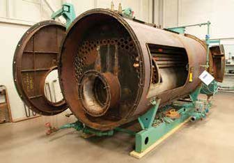
Scotch marine firetube boiler
For an existing boiler whose thickness has been reduced due to corrosion or erosion, continuing code compliance must be checked using the same procedure. This process is best understood with an example.
Consider a situation in which plain cylindrical furnace erosion has been verified by ultrasonic thickness checks in a Scotch marine firetube steam boiler. The boiler is designed with a maximum allowable working pressure (MAWP) of 150 psi. The plain furnace has no stiffening rings, is made of SA -516 Grade 70 steel, and is 91.5 inches long with an outside diameter of 30 inches. Measurements show the furnace has a thickness of 3/8 of an inch. It is desired to know if the 3/8-inch furnace thickness is code compliant with the original design MAWP.
The methodology for determining if the as-found thickness meets code requirements for the boiler is found in Section I, PG-28, and there are two procedures to make this determination. Either PG-28.3.1.2 (a) or PG-28.3.1.2 (b) is used for this depending on the value of DO /t where DO is the tube’s outside diameter and t is the thickness:
- Procedure (a) DO /t ≥ 10
- Procedure (b) DO /t < 10
For our example, DO /t = 30/0.375 or 80, and therefore, the DO /t ratio is over 10, and procedure (a) is used. To use procedure (a), one must first determine the value of L for the situation. L is the total length of a cylindrical component between the lines of support. Using the definition of L given in PG-28.3.1.1, the only lines of support in our simple example are the two tubesheets, which are 91.5 inches apart. If there had been a stiffening ring in the middle of the furnace, then we would have needed to go to Section I, PFT-17, to check if the ring or rings were Code compliant. If found to be compliant, the stiffening ring would have been a line of support that would have reduced the value of L and ultimately increased the allowable external pressure.
The other ratio needed for our determination is L/DO or 91.5/30 or 3.05. Using the DO /t of 80 and an L/DO of 3.05, we go to ASME Section II, Part D, Figure G (see Figure 1). We draw a horizontal line from the 3.05 value on the ordinate (vertical L/DO value) and intersect the DO /t = 80 curve. We drop vertically to the abscissa (horizontal axis) to read a value of A of 0.00056 as required by Step 3 in PG-28.3.1.2.
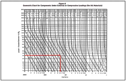
Figure 1: Figure G from ASME Section II, Part D, Subpart 1
Once the A factor is obtained, simply find the external pressure chart for the material, which is listed along with the allowable stresses in Section II, Part D, Table 1A. For SA-516 grade 70, the chart is CS-2 (see Figure 2). We need to assume a temperature to find the B value. The temperature needed is that of the metal furnace. Recall that gases in the furnace may be over 2,000 F. The water surrounding the furnace must remove the heat to keep the metal temperature within material limits. Heat transfer analysis can determine the metal temperature, but more commonly, the temperature is estimated by adding between 100 F and 150 F to the saturation temperature corresponding to the MAWP.
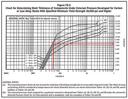
Figure 2, CS-2 from ASME Section II, Part D, Subpart 1
Recall that to find the saturation temperature, 14.7 psi is added to the MAWP to get the allowable absolute pressure. Then, it goes to the saturated steam tables to find the corresponding saturation temperature. For 150 psi, that would be 164.7 psi absolute, which corresponds to 366 F. For simplicity, we therefore assume the design temperature is 500 F. For A=0.00056, the corresponding B is about 7,400.
One then uses the equation in PG-28.3.1.2 Step 6 to determine the allowable external pressure since the A value plots on the right side of the Figure CS-2 material/temperature line:
Pa= 4B/[3(DO /t)] = 4(7400)/[3(80)] = 123.33 psi which is less than the 150 psi MAWP
So, in this case, the plain furnace thickness of 3/8 inches is not sufficient for the MAWP of the boiler.
Some situations tend to complicate the calculations. If the A value had been to the left of the material/temperature line, Step 7 would have required using the equation Pa= 2AE/[3(DO /t)] instead of the one used.
When procedure (b) is required because DO /t is less than 10, it becomes even more complicated. There are similar steps to obtain the B value, which may necessitate calculating an A value when DO /t is less than 4. Procedure (b) also requires the calculation of two different allowable external pressures Pa1 and Pa2 from two different equations.
The Pa2 equation contains a parameter SB which is equal to the lesser of twice the maximum allowable stress value found in
ASME Section II, Part D, Subpart 1, Tables 1A and 1B or 1.8 times the yield strength of the material at the design metal temperature from Table Y-1 in the same Subpart 1 of Section II.
Once Pa1 and Pa2 are calculated, the smaller of the two pressures is the furnace’s maximum allowable external pressure.
As can be seen from the above example of a plain furnace in a Scotch marine boiler, the external pressure calculations are not extensive if stiffening rings are not involved. If needed, the same methodology is used to determine the allowable external pressure for firetubes in a firetube boiler. For plain furnaces or tubes under external pressure, the inspector should be able to use the step-by-step instructions in PG-28 to compute the allowable external pressure for a given thickness.