Given the conservatism normally introduced by simplistic design rules, component or system failures require a confluence of factors related to their design, fabrication, operation, and metallurgy.
Although the objective of The American Society of Mechanical Engineers Boiler and Pressure Vessel Code (ASME BPVC) is “to afford reasonably certain protection of life and property and to provide a margin for deterioration in service to give a reasonably long, safe period of usefulness,” it also recognizes that it “is not a handbook and cannot replace education, experience, and the use of engineering judgment.”
It's clear that the supply chain supporting the thermal fleet possesses an inadequate appreciation and understanding of the consequences associated with the minimum set of requirements published by ASME BPVC. Too many, in fact, regard ASME BPVC and other codes or standards as a de facto “gold standard” that requires no additional requirements to design, fabricate, and construct what should be viewed as a complex set of high-pressure systems without a defined design life. To this end, emerging issues point to the deficiencies that exist when designing components or systems for operation in the time-dependent (creep) range and/or subjected to cyclic operation.
The fabrication of pipe (A-/SA-690) and/ or fittings (A-/SA-234) from rolled and welded plate has long been recognized as a risk given the onset of catastrophic failures starting with the rupture of a stainless steel elbow at Canal Electric in 1970 and subsequent fatalities resulting from the well-known rupture in a grade 11 hot reheat system at Mohave in 1985 [1]. Because new construction codes or standards do not prohibit seam-welded construction, large diameter modern hot reheat piping systems have been fabricated from such product form, including the installation of seam-welded components that were specified as seamless on design drawings.
Access to ex-service components and well-controlled creep testing of seam-welded ex-service material show that grade 91 seam-welded product forms exhibit significant variability in the time to failure (about 75 times) [2]. For a component expected to arbitrarily last 1 million hours, this reduction would result in a mere 15,000 hours of operation, or about two years of baseload service, before a leak or rupture occurs.
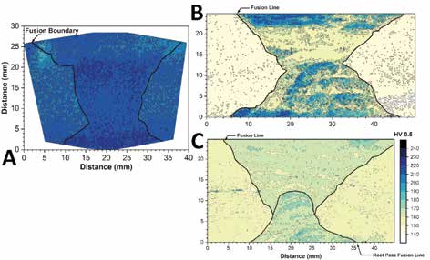
Figure 1: Example of the variability observed in ex-service
long-seam welds (highlighted by black lines) removed for
condition assessment. A properly fabricated seam-welded
pipe is shown in (A), and for a mal-heat treated clamshell
welded elbow at the intrados (B) or extrados (C) welds.
Examples of seam-welds from plants in North America are given in Figure 1, where an acceptable seam-weld from a straight pipe section (Figure 1A) is compared to a clamshell welded elbow where a non-uniform hardness profile is clearly observed (Figures 1B and 1C). It is also apparent that the hardness varies from the intrados (Figure 1B) to the extrados (Figure 1C). Had the elbow been properly heat treated after seam welding, and as is required by the specification, the hardness data should have been very similar to Figure 1A.
Tee intersections designed to ASME B16.9, stamped A-/SA-234, and installed in ASME B31.1 or ASME BPVC Section I systems have exhibited cracks or developed leaks in the girth welds and/or crotch positions in about 37,000 to 150,000 hours of service. The safety concern and total number of events (greater than 100) prompted EPRI’s Generation Sector, for the first time, to issue an industry alert because no other entity is taking the lead on this critical role [3]. To date, an industry-sponsored collaborative EPRI project has documented cracks in tees manufactured from a variety of steels, including the low alloy steel grade 22 and creep strength enhanced ferritic (CSEF) steels such as grade 91, grade 92, and X20 [4]. The spiraling issues in tees are highlighting fundamental deficiencies in several codes or standards, including:
- Inadequate design rules for product forms or components installed in the creep range.
- A-/SA-234 notes: “The forming procedure shall be so applied that it will not produce injurious imperfections in the fittings.” However, fittings have been installed in systems with significant stress concentrations (so-called “vees”) or weld repairs connected to the ID in the crotch position. For CSEF steels, the variation in performance for a tee with a repair versus a tee without a repair is easily a factor of 10 times or more if the repair is merely given a subcritical post-weld heat treatment (PWHT). This means that a tee that might be expected to arbitrarily last 1 million hours in operation may only achieve 100,000 hours of operation. Furthermore, no explicit language mandates that repairs in these tees be documented.
- In multiple examples, tees were stamped as SA-234 WP91 and found to be a different material.
- Tees designed to ASME B16.9 should have weld preparations that follow ASME B16.25. However, many tees have entered service with an inside diameter (ID) profile exhibiting a negative slope or the ID taper intersects the girth weld in a manner that does not follow the details given in ASME B16.25.
- Tee suppliers do not perform integrity calculations to assess the minimum design thickness required in the crotch location. This is critically important given that the material removed in the opening must be placed in the crotch to sufficiently reinforce the tee and ensure performance. Some have indicated that the seamless pipe starting material is two schedules thicker and others have said they obtained pipe 40% thicker than nominal thickness of the piping system. The observed variability suggests that the pipe starting stock is obtained based on what is available to fill the order rather than an engineered approach.
- Tee suppliers are allowed to perform burst tests on carbon steel tees, and at ambient temperature, to validate tee dimensions and design. A single burst test can qualify fittings with a large size range including similar proportioned tees from one-half to two times and a range in t/D from one-half to three times. Neither the material nor the proof test is representative of higher alloyed materials operating in the creep range.
- Tees are frequently placed in high-traffic areas (turbine hall, on walkways on top of heat recovery steam generators [HRSGs] and near valves) where a steam release could introduce significant safety concerns.
- Until the 2024 edition of ASME B16.9 was published, no dimensions of the formed tee were required to be reported. This affects the vast majority of the at-risk population.
- To obtain the necessary dimensional information to help screen tees and prioritize future inspection and/or replacement schemes, significant cost has been incurred, and subsequent findings repeatedly demonstrate the difficulty in obtaining well-documented, repeatable, and trustworthy measurements from service providers. Such observations call into question other critical activities, including flow-accelerated corrosion (FAC) inspection or other balance-ofplant nondestructive evaluation (NDE).
Tee failures are a significant issue in the industry, and recent assessment suggests that 25% of the total installed population is at risk. In the U.S., more than 1,200 possible units are affected, representing thousands of tees. Considering the replacement costs are $500,000 per tee, which is more than 10 times the original cost of the tee itself, the possible replacement costs required over the lifetime of these units are more than $1 billion. Such industry challenges continue to demonstrate the value in implementing improved design requirements for new construction as the operations and maintenance costs to later address the design deficiency can be excessive while introducing mitigatable safety concerns.
Block forgings have been introduced in several geometries, including intersections (predominately tees or wyes) and large bore valve bodies in main steam or hot reheat piping systems. In some large U.S. fleets with dozens or hundreds of valves, entire populations have been replaced with these inadequate designs.
Recently, and due to the large section thickness in valves, cracks have been observed (Figure 2) in one fleet. These cracks are ID-connected and make repair essentially impossible due to the amount of material removal required to gain access to the ID to execute the repair. In the example in Figure 2, the maximum thickness is about 15 inches in the crotch formed by the bonnet and outlet bores. A valve replacement is cost prohibitive (about $400,000), and long lead times of one to two years for replacement are common. This is increasing the need for end-users/ owners to embrace a combination of well-informed fitness for service assessment (FFSA) and periodic re-inspection to validate and refine the assessment.
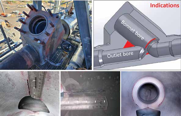
Figure 2: Example of inside diameter connected cracking between the bonnet and outlet bore and in the seat region originating from low cycle fatigue in a large block forging minimally machined into a valve body.
The case study described in Figure 2 continues to be monitored and is providing substantial benefit to the industry regarding the validation of recently optimized FFS approaches for high-temperature components [5]. It is noteworthy to highlight that the reported cracking was for a valve that had been in service for a mere 24,000 hours and 550 cycles after replacing a casting that was in service for about 100,000 hours. Because of the time it takes to machine large block forgings, where 80% of the weight or more may be required to produce a fully contoured profile, suppliers are motivated to remove as little material as possible to reduce the time the component spends in the machining cell. Machining is frequently cited as a choke point in production, so much so that even if a fully contoured part is requested, it may be “no-quoted.”
Flat end caps (see possible designs in Figure 3) have been associated with failures in ferritic and stainless-steel headers and manifolds [6]. Recently documented issues have highlighted several potential complications:
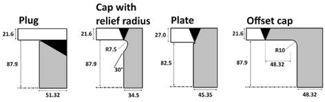
Figure 3: Example of flat header end cap designs.
- HRSG designs feature headers that essentially “butt” together with very little access. Often, the end cap is only accessible over a relatively small circumference and/ or may not be accessible from the end of the header (e.g., from the cap). This results in the incomplete inspection coverage of the weld and/or circumference and introduces significant uncertainty regarding future performance.
- In at least one case study, a portion of the volume in a grade 91 steel design was welded with carbon steel, compromising the creep integrity of the weld. Because this volume was ID-connected, it is undetectable. For perspective, grade 91 steel exhibits a creep life greater than 1,000 times compared to carbon steel for a given temperature and stress.
- Rupture of end caps has been reported in previous decades and recently in the U.S. and Europe for the “plate” and “cap with relief radius” designs in Figure 3. This has not gained more attention because the recent end cap failures were interior to the HRSG and did not eject outside the casing.
- Evidence for fatigue and/or creep damage mechanisms. In the case of creep-dominated damage evolving in a uniform stress field, EPRI evidence suggests that detection may only be possible in the last 20% of remaining life, with the worst case of about 5% of remaining life.
- There is typically no instrumentation installed on end caps. This provides no possibility to assess the contribution of operation, particularly repeated local thermal events, which is critically important in mitigating the factor(s) contributing to fatigue damage.
- Because of the observed failures, there is increasing uncertainty regarding the risk of future failure of other designs (e.g., the plug-in design in Figure 3).
This end cap example clearly challenges “conventional wisdom” that the life management of at-risk geometries is possible by inspection alone and any suggestion along these lines should be revisited. Furthermore, another example of the difficulty in specifying improved designs, a recent new plant successfully avoided the installation of flat end caps in the headers only to find them in the large diameter manifolds. This outcome was a direct reflection of the specification, which did not explicitly state “no flat end caps in headers and manifolds.” The installation of flat end caps on manifolds is an economic consideration given that there are typically no restrictions on access, unlike that for small diameter headers in the HRSG. The onset of data centers, artificial intelligence, and an ever-expanding energy landscape is placing more pressure on the thermal fleet, which still accounts for 60% of the power generation in the U.S.
Keeping units online has a significant risk to the public given that extremes in load demand occur during very hot or very cold spells such that an ever-growing set of run, repair, or replacement options are being explored to maintain an aging fleet during these critical periods. New plant construction, which is expected to increase to meet new load demands, is increasingly driven by the lowest upfront cost and the supply chain, which continues to demonstrate a lack of awareness regarding the minimum requirements in commonly used codes and standards.
Because of the fixation on the lowest upfront cost, it is helpful to revisit the Mohave failure, which not only included fatalities (six) and injuries (10) but also introduced an adjusted-for-inflation impact of $250 million to address the uncertainty across the affected plant and balance of the end-user’s fleet.
Over the last decade, EPRI has endeavored to fill gaps through publicly available technical guidance, such as in [7 and 8], but it is apparent that the scope and magnitude of the problem are systemic and well beyond what EPRI can do unilaterally. Moving forward, more failures are inevitable. Yet, the actions that the industry will take to respond, challenge the status quo, and educate itself on such emerging issues must evolve to ensure we do not introduce preventable risks to the public or plant staff, and/or introduce potentially significant economic consequences.
REFERENCES
[1] 30-Plus Years of Long-Seam Weld Failures in the Power Generation Industry-Perspective and Continuing Challenges with Life Management. EPRI, Palo Alto, CA: 2017. 3002011587.
[2] A. Bridges and J. Siefert. “Variability in the Performance of Grade 91 Longitudinally Seam-Welded Components.” Proceedings of the 6th International ECCC Creep and Fracture Conference, 2023. pp. 303 to 316.
[3] Generation Industry Alert: Tee Intersections. EPRI, Palo Alto, CA: 2023.
[4] Integrated Life Management of Tee Intersections in High Temperature High Energy Piping Systems. EPRI, Palo Alto, CA: 2022. 3002025353.
[5] An Informed Perspective on the Adoption Of Comprehensive Fitness-for-Service in an Integrated Life Management Strategy. EPRI, Palo Alto, CA: 2021. 3002020435.
[6] “Failure incidents on flat header endcaps with stress relief groove and test measures derived from these,” VGB PowerTech 7/2004.
[7] Technical Requirements for High Reliability Fossil Power Plants: Best Practice Guideline for Manufacturing and Construction of Grade 91 Steel Components, 4th Edition. EPRI, Palo Alto, CA: 2024. 3002029866.
[8] Guidelines and Specifications for High-Reliability Fossil Power Plants: Best Practice Guideline for Welding Root Without Purge Gas Using the Gas Metal Arc Welding Process. EPRI, Palo Alto, CA: 2019. 3002015042.