Electrochemical stacks are becoming an increasingly important and common industrial product used in the production of hydrogen and other industrial chemical and energy products.
Unlike galvanic systems, such as fuel cells or primary batteries, that use electrochemistry to output electrical energy, electrochemical stacks are electrolytic systems that consume electrical input energy to convert the physical state of feed material into higher value products.
A wide range of electrolytic systems have been in use for decades, including the chlor-alkali process for the production of chlorine, hydrogen, and caustic soda, and the Hall-Héroult process for the production of aluminum. New applications for electrolytic processes are being developed and deployed, with one major focus being the production of hydrogen using green (renewable) electrical power.
The ability to use electrolysis for the direct production of hydrogen and oxygen from water has been known for over 230 years. Still, there have been significant scientific and industrial developments around electrolyzers since the 1960s, with initial applications for space flight and military systems. Over the past two decades, the technology has advanced to address large scale hydrogen production with plants deployed in the megawatt (MW) scale and installations in development at the gigawatt (GW) scale. These large-scale plants are being used to produce hydrogen for energy storage and for direct feed into other industrial processes, such as ammonia production and steel processing.
There are several types of electrochemical technologies and stacks being used and developed. These include alkaline electrolyzers, proton exchange membrane electrolyzers (PEM), anion exchange membrane electrolyzers (AEM), and solid oxide electrolyzers (SOE). These electrolyzer stacks are assembled from individual cells, typically arranged in electrical series. Each cell consists of an anode compartment, a cathode compartment, and some type of cell separator or membrane. The anode is the electrode where oxidation (loss of electrons) occurs, and the cathode is the electrode where reduction (gain of electrons) takes place.
With the increased production and deployment of electrolyzers at the MW and GW scales, industry rules and regulations are now being written to ensure the equipment is designed, built, installed, and inspected in accordance with the associated risks. One of the most significant factors in the design and deployment of electrolyzers is the safe containment of pressure.
Alkaline-based electrolyzers have been used in industrial applications for decades on a large scale, but these systems have been primarily operated at lower pressures with balanced pressure between the anode and cathode compartments. Both PEM and AEM systems can operate with high output pressures (50-plus bars) as well as high differential pressures between anode and cathode compartments. New alkaline systems are also being developed with the ability to operate at high system pressures while maintaining balanced pressures between anode and cathode compartments.
The unique construction methods required to optimize electrochemical performance in electrolyzer stacks create a challenge in meeting existing pressure vessel codes of construction. New codes and standards have been created to provide a common set of design and testing guidelines to provide a path for authorities having jurisdiction to evaluate products based on standard codes of construction.
Due to the potentially high internal cell pressures, electrolyzers are now considered pressure vessels. For deployment in Europe, stacks must be CE marked and meet design and testing requirements, per the Pressure Equipment Directive. For the U.S. and other markets, electrolyzers are considered pressure vessels under The American Society of Mechanical Engineers Boiler and Pressure Vessel Code (ASME BPVC) Section VIII and should be stamped as such unless exempted with an internal cell size less than 6 inches and/or a maximum pressure less than 15 psi.
An electrochemical stack working group within ASME BPVC Section VIII, led by Dr. Kang Xu, is responsible for the development of code cases specific to electrochemical stacks. Code case 3078 was published in December 2023 and provides design and testing requirements for code stamping of electrolytic electrochemical stacks as U stamped pressure vessels.
Various types of electrolyzers have different internal cell structures based on different technologies, methods of construction, materials of construction, and operating conditions. Pressurized stacks generally have structures similar to plate heat exchangers, with multiple cells compressed between ported end plates that are loaded by tensioned tie rods or bolts. While a full explanation and comparison of all possible electrolyzer stack configurations is not possible in this article, Figure 1 shows a typical layout of a PEM-style pressurized electrolyzer for the electrolysis of water into hydrogen and oxygen.
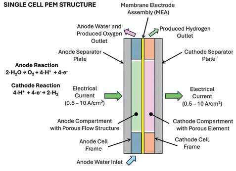
Figure 1: Single cell PEM structure
Working from left to right, the cell consists of a conductive separator plate, the anode compartment, a membrane electrode assembly (MEA), the cathode compartment, and then another conductive separator plate. The spaces within the anode and cathode compartments are not empty voids; they are filled with conductive porous structures, providing an electrical path for the conduction of current across the anode and cathode compartments within each cell.
The conductive porous structures also provide mechanical support for the membrane when loaded with differential pressure between anode and cathode compartments. The porous structure allows for the flow of water through the anode compartment and hydrogen through the cathode compartment. If multiple cells are configured in series, one side of a separator plate may be in contact with the cathode of one cell, while the other side of that plate may be in contact with the anode of the next cell. The outer edges of each anode and cathode compartment have a frame structure that provides pressure sealing and porting for fluid flow into and out of each cell.
Electrical current is driven through the cell from left to right with current densities in the 0.5-10+ A/cm2 range. The thickness of the anode and cathode cells depends on the specific design and application, but they must always be sufficiently thick to allow for water flow through the anode and production hydrogen flow from the cathode. High purity water is pumped into one side of each anode compartment.
Some of this water is split by electrolysis into hydrogen and oxygen, but the majority of the pumped anode water in a PEM electrolyzer flows through the anode cell and back out to the electrolyzer system. This anode water flow removes excessive heat from each cell to maintain temperature control and removes produced oxygen from the anode compartment. If the produced oxygen is not removed from the cell during operation, the oxygen will form gas pockets that isolate regions of the MEA and reduce the available active area. The hydrogen evolution reaction occurs on the catalyst surfaces on the cathode side of the MEA.
The hydrogen produced in the cathode from this reaction can be at a much higher pressure than the anode compartment due to electrochemical compression of the hydrogen protons as they are driven across the membrane by the driving cell voltage. The pressure in the cathode compartment is controlled by an external back pressure regulator placed on the cathode output lines of the stack.
The edge frames of the electrolyzer cell are ported to allow for anode supply and return flow as well as cathode exit flow. Figure 2 shows the flow porting for a single cell with the top separator plate removed.
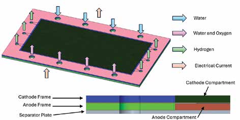
Figure 2: Single cell ported flow
Figure 3 shows the flow within a cathode compartment. Hydrogen is produced over the entire active area and flows through the porous structure to exit ports on either side of the cell.
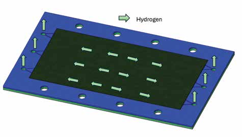
Figure 3: Flow within a cathode compartment
Figure 4 shows the flow in an anode compartment. Water flows from ports on one side of the cell across the anode compartment and then exits as a flow of water and oxygen through ports on the other side of the cell.
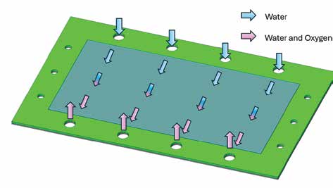
Figure 4: Flow across an anode compartment
Multiple cells can be mounted in series in a single stack. In this case, the cells are mounted in electrical series, and the number of cells in a stack can vary from a few cells up to a few hundred cells depending on the stack configuration and target capacity. Each cell can operate with a driving voltage in the range of 1.5-2.4 volts direct current (VDC), so a large stack can easily reach voltages of 400-plus VDC across all cells in series. Cells mounted in electrical series usually have fluid paths in parallel such that all anode compartments are connected to common supply and return ports, and all cathode compartments connect to a single common stack outlet.
The cells are mounted between end plates, but due to the electrical supply and return requirements, additional components are mounted between the cells and end plates. Figure 5 shows a side view of a PEM stack. At least one end of the stacked cells must be electrically isolated from the end plates. This is done by placing an insulating plate (polymer, ceramic, or composite) between the end plate and a conductive plate below the first cell in series. This conductive plate, often referred to as a current collector, extends past the edges of the active cells and provides current/voltage connection points for an external DC supply. The current collector is in direct contact with the separator plate of the first cell in series.
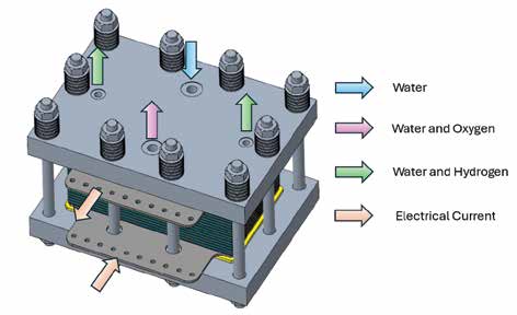
Figure 5: Side view of PEM stack
On the other end of the cells in series, a similar current collector provides for the other connection point to the external DC supply. While at least one of the current collectors must be electrically isolated from the end plates, the other plate may or may not be electrically isolated depending on the stack and DC supply (rectifier) configuration. If the second current collector is not electrically isolated from the end plates, then the current collector may be in direct contact with the end plate, and connection points may be incorporated directly into the end plate. In this configuration, this non-isolated current collector is held at earth potential. The second current collector may also be electrically isolated from the end plate using a second insulating plate. This allows for both current collectors to be held at voltage potentials different from the end plates and enables multiple stacks to be mounted in electrical series, which can reduce system rectification costs with stack voltages up to 1500 VDC.
At least one of the current collectors is ported to allow for anode and cathode flow into and out of the stack. It is possible to maintain electrical isolation across these ports due to the high electrical resistance of the fluid flowing in these ports. Port size and type are dependent on stack pressures and required flow to support stack operations. All the stack cells and secondary components, such as insulator plates and current collectors, are compressed between the end plates using loaded tie rods. Spring elements such as Belleville disc springs are used on the tie rods to allow for thermal expansion of cell components without generating excessive end plate compressive loads. Cell frames on individual cells are often polymeric and have much higher coefficients of thermal expansion than the other metallic components. The use of disc springs accommodates these high thermal expansion materials and compensates for gasket creep over time. Stacks typically operate at elevated temperatures, as the electrochemical processes can be more efficient as temperature increases, and stack temperatures can exceed 80 degrees Celsius.
Figure 6 shows an isometric view of a PEM stack, with anode and cathode ports on the top end plate. The current collectors extend past the edge of the end plates to enable easy cable or busbar connection to the stack electrical supply.
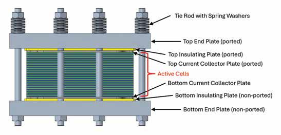
Figure 6: Isometric view of PEM stack
The above stack description covers a general layout for PEM-based water electrolyzer and is in no way meant to imply that all electrolyzers follow this method of construction. Cell construction and configuration can vary significantly depending on application and technology, and electrolyzers can be constructed for multiple uses well beyond just water electrolysis for hydrogen production.
ASME BPVC Section VIII Code Case 3078 allows for the use of a wide range of designs and materials for cells and other active stack components between the end plates. The primary load-bearing components, such as end plates, tie rods, and nuts, must be designed in accordance with the rules in ASME BPVC Section VIII in order for the stack to be a U stamped vessel. Materials used in the construction of the primary load-bearing components must also be compliant with Section VIII rules. The ability to produce stacks as ASME U stamped pressure vessels provides a code of construction to ensure safe equipment design, installation, and operation.