The most common failure modes observed at the National Board Pressure Relief Laboratory and some possible causes of these failures were examined in the spring edition of the BULLETIN.
Two possible recurring causes of failure modes were insufficient test stand volume and poor adjustment ring settings. To expand upon this, an article will be devoted to each issue. In this article, the effects of adjustment ring settings on valve performance will be discussed, specifically focusing on the physical operation of valve components to help understand the function of adjustment rings.
Principle of Spring-Loaded Valve Operation
The basic principle behind the operation of any pressure relief valve is the idea of a force balance between the system pressure that acts on one side of the valve’s disk and the seating force on the other.
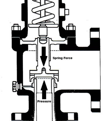
Figure 1: Diagram of force balance
on a spring valve.
In the case of a spring-loaded valve, this seating force comes from a compressed spring. The spring rate and compression provide a downward force that the pressure must overcome to open the valve (see Figure 1). Since pressure is, by definition, force over area, the amount of force being applied due to pressure is the system pressure multiplied by the area of the seating surface. Once the force of the pressure acting on the valve’s disk begins to overcome the spring force, the disk begins to lift. Once the disk starts to lift, the area on which the pressure is acting increases, and the valve pops open.
Physical Effect of Adjustment Rings
As the valve pops open and fluid begins to flow through it, the force acting on the disk changes from the force of the static system pressure to a dynamic force caused by the fluid flow through the valve.
The force of the flowing fluid holds the valve open until the system pressure decreases enough for the spring force to overcome this dynamic force and reclose the valve. The valve’s rings direct and capture this force in an area called the huddling chamber. The settings of the rings dictate how the flow is directed and how much is captured. Good ring settings result in reliable valve operation, full relieving capacity, and finely tuned opening and reclosing pressures. Bad ring settings can lead to unstable operation, insufficient relieving capacity, or both.
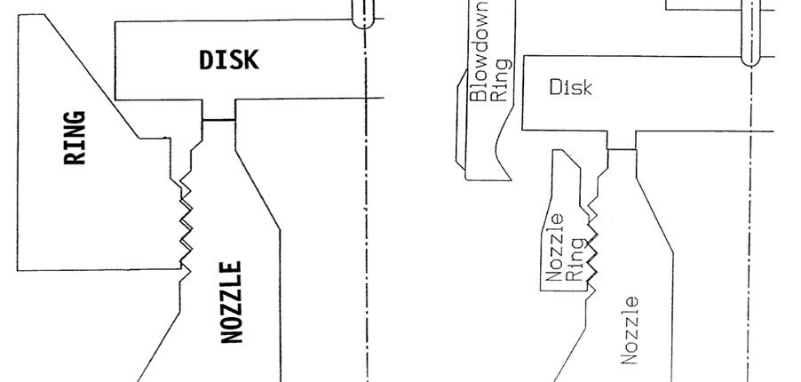
Figure 2: Single ring design (left) and dual ring design
The design of valves with adjustment rings varies slightly but can be broken into two categories: single ring designs and dual ring designs. A comparison is shown in Figure 2. In the single ring design, the huddling chamber is fixed by the disk and holder, and the adjustment ring threads onto the valve’s nozzle. In dual ring valves, there is a lower ring on the nozzle, similar to a single ring valve, but there is also an upper ring (referred to as a blowdown ring in Figure 2) that allows for more variability in the huddling chamber.
Single Ring Designs
In a single ring design, the nozzle ring functions by directing the flow of fluid up into the huddling chamber of the valve, which is a fixed geometry. When the ring is raised closer to the disk, the flow is concentrated more narrowly into the huddling chamber. This provides a crisp and forceful popping action by increasing the amount of force acting upward on the disk. This means the spring will need to overcome this increased force to reclose the valve, so the pressure at which the valve can reclose becomes lower.
A large difference between the opening and reclosing pressures (referred to as blowdown) can be undesirable for users, as it will result in more lost fluid from the system. To shorten the blowdown, the ring can be lowered, allowing the flow of the fluid to spread out more from the nozzle and impact less directly on the huddling chamber. Less force directed upward, however, will mean less of a crisp, forceful popping action. This increase between the valve’s initial leakage and full pop is referred to as “simmer” and can lead to inconsistent operation or set pressures outside of tolerance. If the ring is moved too low and not enough force is directed into the huddling chamber, the spring may not fully compress, and the relieving capacity of the valve can be decreased. This situation can also lead to flutter or chatter during operation because the force of the flow cannot provide enough force to the disk to maintain full lift, leading to the valve beginning to close, then rapidly popping open again. Chatter can damage the valve’s seating surfaces and cause leaks and undue cyclical stress on support structures for vessels and piping.
Dual Ring Designs
Dual ring valves allow for variability of the huddling chamber by allowing the geometry to be changed by raising or lowering the upper ring. As the upper ring is lowered, more fluid is captured, directing more force into the disk. Conversely, when the upper ring is raised, less fluid is trapped in the huddling chamber, decreasing the force the spring will need to overcome to reclose the valve. By fine-tuning the upper and lower ring settings, a dual ring valve can achieve a shorter blowdown without sacrificing the forceful popping action as seen in the single ring design. The effects of a poor setting on the upper ring may present slightly different than a poor setting of the lower ring. If the upper ring is too high, the huddling chamber can’t correctly capture the force from the fluid flow, leading to a weak pop and low lift. This can also be a cause for chatter or flutter, as mentioned earlier. Care also must be taken not to position the upper ring too low. If the upper ring is too low, it can restrict the flow path and prevent the valve from achieving its full relieving capacity.
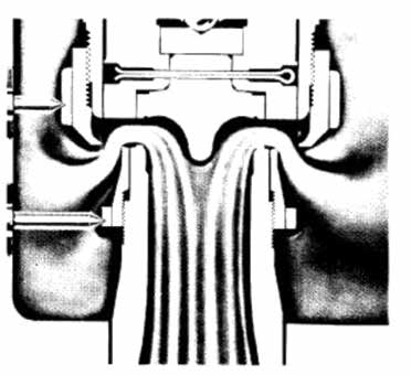
Figure 3: Fluid flow through a dual ring
valve on a spring valve.
When this happens, the valve will exhibit a strong popping action and a high spindle lift. Observing these characteristics may lead to the assumption that the valve is functioning properly, but, in reality, the fluid is being trapped in the huddling chamber, causing excessive lift while decreasing the relieving capacity.
Liquid Applications
Liquid applications usually require different ring settings than compressible fluid applications, such as air, gas, or steam.
Incompressible fluids do not expand as they flow from high to low pressure like compressible fluids. This means that the internal reaction forces within the valve will be different for incompressible, liquid applications. Liquid service valves with adjustments are typically single ring designs, and the proper setting of the ring is critical to ensuring the valve operates as intended.
One of the more commonly observed failure modes in liquid valves is when the valve meets set pressure tolerance but does not fully open within the code-specified overpressure tolerance. The set pressure for a liquid valve is often defined as “first steady stream,” which is when the liquid discharged from the valve forms a vertical stream about as thick as a pencil. As the pressure continues to increase, the force of the flowing water will overcome the spring force, and the valve will exhibit a “popping” or “gushing” action. If the ring is positioned incorrectly on a liquid valve, the flow will not be directed upward into the disk properly, and the pressure required to gush the valve can exceed code-specified overpressure tolerance. In the laboratory, this results in a failure, but in service, it can result in a disaster.
Purpose of Adjustments
After considering the different ways a ring adjustment can go awry, you may ask why even allow for adjustment at all? Why not design the valve with a fixed geometry for the flow path and eliminate the chance of being set wrong? The answer is that some valves are designed with a fixed flow geometry. However, each valve’s performance will vary with its unique combination of pressure, relieving capacity, and application. One flow geometry will not always respond exactly the same for every set pressure or application, even for the same size and design.
Internal reaction forces of the fluid flow vary with flow rate, fluid properties, and pressure, and ring adjustments can help correct for these variations. The application in which the valve is used can also impact its operation or necessitate a longer or shorter blowdown. End users may also have specific requirements for blowdown that require fine-tuning. Valve manufacturers give recommendations for ring settings, which can vary based on model, size, and pressure and can be used as a starting point and then modified slightly as needed.