Combustion Air Requirements:The Forgotten Element In Boiler Rooms
William H. Axtman
President of Gray Gull Associates, Inc.
Retired executive director of the American Boiler Manufacturers Association
Category: Operations
Summary: The following article is a part of the National Board Technical Series. This article was originally published in the Winter 1994 National Board BULLETIN. (6 printed pages)
INTRODUCTION
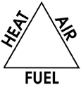
We are all familiar with the combustion triangle containing the three elements required for combustion to take place. These elements are: fuel, heat (ignition) and air (Figure 1). The requirement for fuel is obvious. The requirement for ignition is equally obvious. The requirement for air is somewhat less obvious and too often ignored.
FIGURE 1
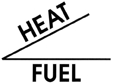
If one of these three elements is removed, the combustion process stops and the combustion triangle collapses (Figure 2). A good analogy is an automobile with a dirty carburetor air filter. When this filter gets dirty enough, the engine sputters and wheezes. If the filter is too dirty, the car won't run.
FIGURE 2
This article considers just how much air is required for proper combustion, where air intake louvers are located, and how they are sized. This is most important, an inadequate air supply can lead to poor combustion performance and even to boiler furnace explosions.
REASON FOR INSTALLING PERMANENT AIR INTAKES
Although the need for permanent air intakes should be obvious, the requirement is ignored too frequently. Temporary air intakes such as open boiler room windows can be closed (and often are when persons in the boiler room are feeling cold), cutting off the boiler's air supply.
When the combustion air supply is closed off, the fire starts to smoke as the air supply is exhausted. Incomplete combustion occurs and carbon monoxide is generated. The fire then goes out, but often before the flame detection system can act to close the fuel safety shutoff valve(s). The accumulation of fuel is re-ignited as oxygen seeps in through cracks and crevices; a furnace explosion frequently occurs with disastrous effects on personnel and property.
An adequate combustion air supply is therefore a requirement to minimize the possibility of a furnace explosion.
SAFETY AND BUILDING CODES COVERING COMBUSTION AIR INTAKE
Several safety codes such as the National Fire Protection Association's standards, NFPA 54 - National Fuel Gas code, NFPA 31 - Installation of Oil Burning Equipment, and the American Society of Mechanical Engineers (ASME) CSD-l Controls and Safety Devices for Automatically Fired Boilers have sections covering the requirements for combustion air intakes. In addition, building codes such as the Building Officials and Code Administrators International (BOCA) National Mechanical Code and the Standard Mechanical Code published by the Southern Building Code Congress International (SBCCI) have air requirements for combustion. These requirements are summarized in Table 1.
LOCATING AND SIZING COMBUSTION AIR INTAKES
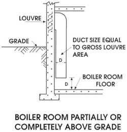
When boilers are installed in a confined space such as a boiler room, two openings communicating directly with the outside are required. One opening is located high in the outside wall. The second opening is located close to the floor. If the boiler room is located partially or entirely below grade, a duct is provided from the lower opening terminating at a point equal to the depth of the duct above the floor (see Figure 3).
FIGURE 3
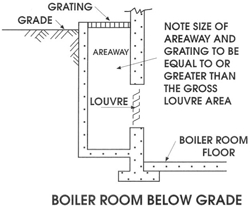
An outside window well or area way can also be utilized (see Figure 4).
FIGURE 4
When sizing these openings, the total fuel input rate of all fuel-burning devices located in the boiler room must be considered. The Btu rate per hour of all boilers at maximum burning rate, plus other devices such as water heaters, are used to size air openings and their associated duct work. Sizing parameters are show in Table 1.
The outside air openings may be protected by louvers or grills. However, the blocking effect of the louver or grill must be considered, and sizing must be done based on its free area. If a protective mesh is used, the mesh must be no smaller than 0.25 inch to minimize dirt build-up or obstruction.
TABLE 1
| Boilers Installed in Confined Space All Air from Outside |
NFPA 54
gas |
NFPA 31
oil |
BOCA
all |
SBCCI
gas & oil |
SBCCI
solid |
| Minimum No. openings required |
2 |
2 |
2 |
2 |
2 |
| Outdoor opening, sq. in./Btuh |
1/4000 |
1/4000 |
1/4000 |
1/4000 |
2/1000 |
| Vertical ducts, sq. in./Btuh |
1/4000 |
1/4000 |
1/4000 |
1/4000 |
- |
| Horizontal ducts, sq. in./Btuh |
1/2000 |
1/2000 |
1/2000 |
1/2000 |
- |
| Ducts same as opening |
yes |
yes |
- |
yes |
- |
| Minimum duct dimension, inches |
3 |
3 |
3 |
3 |
3 |
| Louver & grill free area |
opening |
opening |
- |
- |
opening |
| Free area allowance, wood* |
20-25% |
20-25% |
25% |
- |
- |
| Free area allowance, metal* |
60-75% |
60-75% |
75% |
- |
- |
| Damper interlocked |
yes |
yes |
yes |
- |
- |
| *use manufacturer's free area rating when available. |
If dampers are fitted to these intakes for energy conservation or other reasons, they must be interlocked so the burners cannot be fired unless the dampers are in the open position.
The upper opening provides a means of ventilating the boiler room. The use of exhaust fans in boiler rooms is not recommended, especially if the use of the fan places the boiler room under negative pressure. Such installations should be specially engineered and acceptable to the authority having jurisdiction.
The reason for having the air intake opening either near the floor or being provided with a duct terminating near the floor is to allow cooler outside air to enter the boiler room. If only one opening was provided, heat build-up in the boiler room would reduce the density of the air which, being lighter than cold outside air, would escape through the single opening. This action would cause a negative pressure condition which in turn would cause a down draft in the chimney and breaching adversely affecting combustion. The use of two openings with one located near the floor avoids this situation.
ADJUSTMENTS FOR ALTITUDE
Installations located more than 1000 feet above sea level must adjust the sizing of the air supply openings and ducts for altitude. An adjustment of an additional 3.5 percent per 1000 feet of altitude may be used.
BOILER MANUFACTURERS' RECOMMENDATIONS
Most boiler and burner manufacturers have procedures for sizing combustion air supplies included in their installation instructions. These instructions can be followed, however, caution is required as local codes may supersede the manufacturer's instructions.
Specially engineered combustion air intake systems can be used if they are acceptable to the authority having jurisdiction.
CONCLUSION
Adequate air supply is critical for proper boiler operation. The requirements of the pertinent codes must be adhered to in order to assure good operation. If this is accomplished, a more efficient and safer installation will result.
REFERENCES
- NFPA 54 - National Fuel Gas Code, 1992, section 5.3 Air for Combustion and Ventilation.
- NFPA 31 - Installation of Oil Burning Equipment, 1992, section 1-5 Air for Combustion and Ventilation.
- ASME CSD-1- Controls and Safety Devices for Automatically Fired Boilers, 1992 with addendum 1a 1993. section CG-260 Combustion Air.
- BOCA - National Mechanical Code, 1990, article 10, Combustion Air.
- SBCCI- Standard Mechanical Code, 1991, section 305 Combustion and Ventilation Air.
- American Society of Heating, Refrigerating and Air-Conditioning Engineers (ASHRAE) Handbook - Fundamentals, 1993, Chapter 15, page 15.9 Air For Combustion.
Editor's note: Some ASME Boiler and Pressure Vessel Code requirements may have changed because of advances in material technology and/or actual experience. The reader is cautioned to refer to the latest edition of the ASME Boiler and Pressure Vessel Code for current requirements.