Thermally Induced Stress Cycling (Thermal Shock) in Firetube Boilers
Geoffrey M. Halley, P.E.
SJI Consultants, Inc.
Winter 1998
Category: Design/Fabrication
Summary: The following article is a part of National Board Classic Series and it was published in the National Board BULLETIN. (5 printed pages)
The problem of thermally induced stress cycling (loosely referred to as thermal shock) has been apparent for many years, particularly in boilers installed in hot-water heating systems. The term "shock" suggests a sudden impact type failure, which in the vast majority of cases is far from what actually happens. Most failures of this type occur over a period of time, sometimes as short as a few weeks, and sometimes considerably longer. Failures are typically of the metal fatigue type, and are caused by thermally induced stress cycling of the boiler structure.
Equipment manufacturers and system designers have devised many approaches over the years to combat this problem. Some have been successful to varying degrees, and some have demonstrated a lack of understanding of the failure mechanism.
Although the effects of thermally induced stress cycling can be seen in various types of boilers (e.g., firetube, cast-iron sectional and watertube), this article will be limited to an explanation of the failure mechanism and preventive measures in horizontal firetube boilers of the Scotch and firebox types. Some remarkable similarities have been noted, however, between the failures in the water legs of firebox boilers and the rear sections of cast-iron sectional boilers.
Data has been acquired as a result of both laboratory stress analysis and field test programs, from which it will be seen that failures are many times the result of ongoing conflict between energy conservation requirements imposed on the control system designer, and the requirements of the boiler manufacturer to protect the structural integrity of the boiler.
In some cases, problems have been resolved simply by resetting temperature control points, while in more severe cases, extensive system modifications may be necessary in order for the goals of the control system designer and the boiler manufacturer to be met.
Thermally induced cyclic stresses are due to the resistance of the boiler structure to movement caused by thermal expansions and contractions within the boiler. The stresses occur every firing cycle (burner on, burner off), in varying magnitudes. Failures of this type may appear as leaks at the tube-to-tubesheet joints, cracked tubesheet ligaments, or broken stays. Obviously failures of this type, while not likely to be catastrophic in nature, can be extremely serious in terms of downtime and repair costs.
Factors Affecting the Magnitude of Thermally Induced Stresses
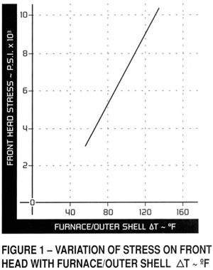
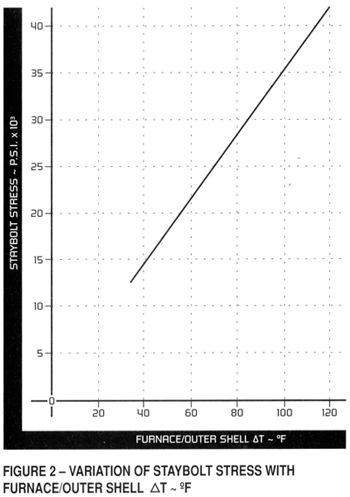
Scotch marine and firebox-type boilers, heavily instrumented with strain gauges and thermocouples, were subjected to varying operating conditions in a laboratory environment where a simulated building heating system had been created. The findings in each case were similar, as shown in Figure 1 and Figure 2, which show the variation of outer fiber or surface stress on a front head at the furnace/head junction of a Scotch boiler and a stay in the side water leg of a firebox boiler. It should be noted that the stresses measured are bending stresses and as such, will be tensile on one side of the plate or stay. The stresses will pass through a neutral axis in the center of the plate or stay and will be compressive on the opposite side, thus mean stress is half the measured outer fiber stress. Figure 1 and Figure 2 both show stress to be directly proportional to the mean temperature difference between the furnace and the outer shell of the boiler, therefore it is purely a function of the differential expansion between the furnace and the shell.
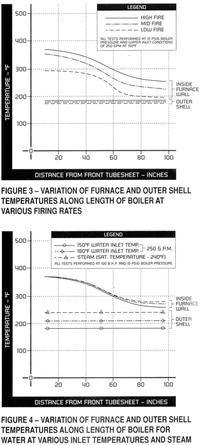
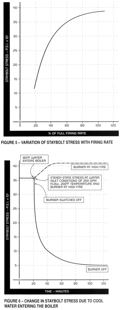
The manner in which various operating parameters affect furnace and shell metal temperatures is shown in Figure 3 and Figure 4. Figure 3 shows how firing conditions influence the furnace metal temperatures, while Figure 4 shows how waterside conditions will affect the shell temperature. It can be deduced that a low-pressure steam boiler will typically be a lower-stressed boiler than the same boiler operated in a hot-water system (unless of course the return water temperature is raised sufficiently to produce similar bulk water, or shell temperatures, as that of a steam boiler). The effect of burner firing rate on stress level is shown in Figure 5, from which it will be seen that low-fire stresses are typically 30% to 35% of the high-fire stress.
Because of the fact that the nucleate boiling occurs around the furnace of firetube boilers, a further factor affecting the furnace metal temperature (besides firing rate) is the boiler pressure. It is for this reason that, in high-rise buildings, the boiler should either be located on the top floor of the building, or isolated from the building pressure by means of a heat exchanger.
Taking the effect of furnace-to-shell metal temperature difference on stress level to a conclusion, it would seem obvious that if the burner is not firing, then the furnace and shell should be at essentially the same temperature and the thermally induced stress will approach zero. This is demonstrated in Figure 6 , in which a firebox boiler operating under steady state conditions at a 200 degrees F. water return temperature suddenly is subjected to a slug of cooler (160 degrees F.) water entering. It will be seen that the stress level on a water leg stay increases if the burner is firing, or conversely approaches zero if the burner is shut off. Obviously the cooler the water entering, the larger the increase in stress level.
To summarize the above discussion, it is known that failures due to thermally induced stresses (or thermal shock) are fatigue failures, and as such are cyclically dependent, one cycle being one on-off cycle of the burner. We also know that the stress magnitude is dependent upon the T between the furnace-metal temperature and the shell-metal temperature. The factors affecting furnace-metal temperature are:
- Burner firing rate - higher firing rates mean higher temperatures.
- Boiler pressure - higher pressures mean higher temperatures.
The only factor affecting shell-metal temperature is the bulk water temperature of the boiler. This is a function of the return water temperature and flowrate, and also burner firing rate. Obviously, low bulk water temperatures mean low shell-metal temperatures and vice versa.
Field Operating Conditions
Studies into the operation of known problem installations in the field revealed the following:
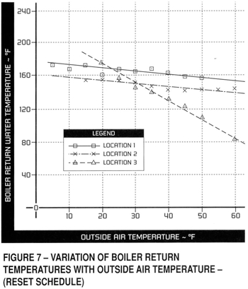
- All systems had a reset schedule on the building system temperature, based on the outdoor ambient temperature. This resulted in boiler return temperatures being lower than manufacturers' recommendations. Three typical examples are shown in Figure 7, from which it will be seen that return temperatures as low as 90 degrees F. were experienced in mild weather.
- Boilers were oversized for the load, especially during the mild weather of spring and fall. This resulted in cyclic operation of the boiler, one of the key ingredients for a fatigue failure.
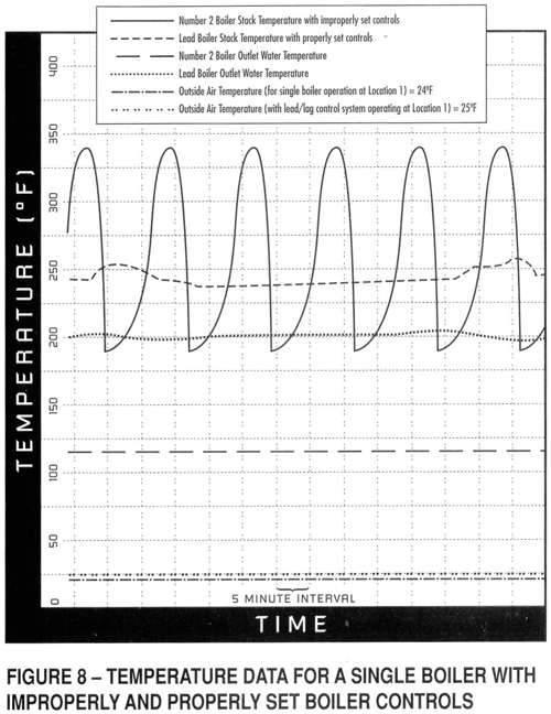
- Burner operating and modulating controls were improperly set in relation to one another, resulting in high burner cycling rates to high firing rates. An example of this type of operation is shown in Figure 8. Operation of the same boiler at the same outdoor temperature, when the burner controls had been properly set, is also shown in Figure 8, from which it will be seen that cyclic operation had been eliminated for the outdoor temperature in question. Burner firing rate, and hence stress level, was also considerably reduced. In this particular case, no further failures were experienced.
- Electrical load shedding is a factor to be considered in systems where air handling units are shut down for many hours, allowing large volumes of water to cool down. On system restart, large volumes of relatively cold water can enter the boiler in a short period of time, unless the proper preventive measures are taken.
Protective Measures Against Thermally Induced Stress Cycling (Thermal Shock)
It may not always be possible to design a boiler structure within the confines of boiler design codes, and have thermally induced operating stresses below the fatigue limit of the steel being used. This is especially true when one considers that heating system operating parameters are most often unknown to the boiler manufacturer. It then becomes necessary for the boiler manufacturer to set guidelines for the system-and-controls designers to use, in order to minimize these effects.
Typically these guidelines may include:
- A minimum water return temperature to the boiler.
- A minimum water flowrate through the boiler.
- Recommendations as to how to set burner controls to maximize the boiler shell temperature for a given operating pressure, and minimize the number of operating cycles and the burner firing rate, for a given load condition. Prolonged periods of low firing rates are preferred to a series of on-off cycles to high firing rates.
Implementation of the Guidelines
Different boiler manufacturers may offer slightly varying guidelines as a means to overcoming the problems associated with thermally induced stress cycling. Thus, the following discussion should be taken as a generalization. Individual boiler manufacturers' recommendations will override what follows.
As we have seen above, the recommendations should address the two major criteria in fatigue failures, namely reducing the magnitude of the stresses induced (reducing furnace-metal temperature to shell-metal temperature ?T) and reducing the number of stress cycles (burner firing cycles).
Reducing stress magnitude will most often be achieved by raising the temperature of the boiler shell (i.e., raising the bulk water temperature of the boiler) and attempting to isolate the boiler as much as possible from system temperature changes.
This can be achieved in two steps:
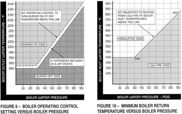
- Correctly setting the burner operating control in relationship to the boiler operating pressure, and limiting the temperature of the water returning to the boiler below which the burner would be held at low fire, to reduce stress levels. Examples of these guidelines are shown in Figures 9 and 10, respectively. It should be noted that in some systems, design or operating parameters may preclude the use of low-fire hold devices, whether they be time delays or aquastats, due to the fact that the system will be unable to attain its design operating temperature without the burner being allowed to achieve higher firing rates.
-
The common method of minimizing the effect of heating system temperature changes on boiler bulk water temperature is to use a two-loop system.
One loop of the two-loop system is the boiler loop, which is operated at a constant temperature set in accordance with the guidelines above. Typically, this loop would have a minimum flow requirement imposed by the boiler manufacturer. (In the absence of a detailed knowledge of system operating parameters, a rule of thumb is 0.5 to 1.0 gpm per Bhp, depending upon the boiler manufacturer.) This breaks up any tendency to temperature stratification within the boiler, as well as attempting to achieve the desired level of shell temperature.
The second loop is the building system(s) loop in which the temperature will vary in response to an outdoor temperature reset schedule, and in which flowrate may vary to meet energy conservation criteria.
The interface between these two loops is usually either a three- or four-way valve, to which the building system temperature reset schedule is applied. This allows sufficient water from the hot boiler loop to blend with the cooler water returning from the building heating system to achieve the temperature requirements prevailing at any given time. There are obviously many system configurations that will meet this basic concept.
Reducing the number of stress cycles is achieved first by correctly setting the burner operating and modulating controls in relation to one another. This means that the modulating control must not send the burner to the high-fire position immediately after the operating control has initiated the firing sequence, and the main flame is established. (Reference Figure 8)
The second method of reducing the number of stress cycles is to carefully select boiler sizes and burner turndown rates (high-fire fuel flow/low-fire fuel flow) for a given boiler room. The heating season load profile must be matched, paying particular attention to the low-load segments in the spring and fall, as it is in these periods when there will be a tendency for the boiler/burner to cycle on and off more frequently. Selecting the number and size of boilers to suit a seasonal load profile may mean that the boilers will not all be of equal size but rather a smaller boiler will be used in the spring and fall with larger boilers handling the high load of the winter months. Alternatively, a large number of smaller boilers may be used with a lead/lag control system (the modular approach). Properly selecting boiler sizes for a seasonal load profile has the added benefit of energy savings in terms of reduced heat loss from the boiler shell.
It is always possible that financial constraints will preclude the ideal size selection of boilers and their numbers for a given installation. However, if this is kept in mind as a goal, a better system should be the result.
Conclusion
Failures caused by what is commonly referred to as thermal shock are actually fatigue failures caused by thermally induced stress cycling. They are not an indication of boiler design or manufacturing deficiencies, as has been inferred on occasion, but are rather due to the manner in which the heating system has been designed, controlled or operated. In some cases, a lack of knowledge may be the reason, while in others financial constraints may play a part.
Editor's note: Some ASME Boiler and Pressure Vessel Code requirements may have changed because of advances in material technology and/or actual experience. The reader is cautioned to refer to the latest edition of the ASME Boiler and Pressure Vessel Code for current requirements.