Pressure Vessel Fatigue
Francis Brown
Senior Staff Engineer
National Board
Category: Design/Fabrication
Summary: This article was originally published in the Fall 2010 National Board BULLETIN.
Section VIII, Division 2 of the ASME Boiler and Pressure Vessel Code (ASME 2010) defines fatigue as “… conditions leading to fracture under repeated or fluctuating stresses having a maximum value less than the tensile strength of the material.”(1) Fatigue damage in a metal is a progressive, localized, permanent structural change. This article takes a more detailed look at metal fatigue including testing for fatigue, conditions affecting fatigue life of a pressure vessel, and examining vessels for signs of fatigue.
According to Harvey(2), the important factor is number of stress repetitions, not time in service. Fatigue in metals is a progression beginning with submicroscopic changes in grain structure of the metal, and consists of three main stages: crack initiation, crack propagation, and rupture. Once initiation of a crack occurs, the crack grows a finite amount with each stress cycle until the remaining cross sectional area is so small rupture occurs. Straightening the wire in a paper clip and bending the wire back and forth about a point until failure is a common example of fatigue.
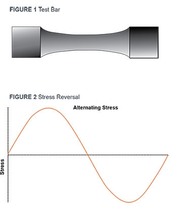
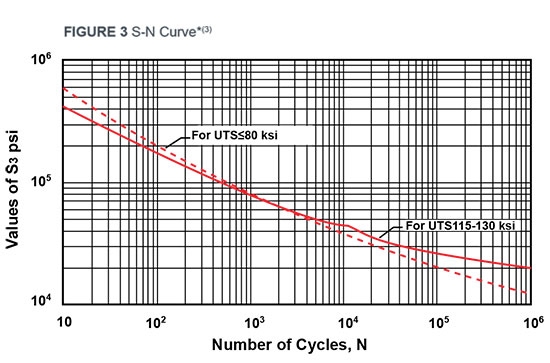
Before fatigue life of a pressure vessel can be determined, fatigue life of material(s) of which it is constructed (number of cycles at a given stress level) must be known. Fatigue life of a material is determined by testing many identical samples to failure. Test samples are highly polished round bars as identical to each other as manufacturing can make them (see Fig. 1). A test bar is rotated with load applied so a fiber at the surface of the bar is in tension and then in compression as the bar rotates such that there is a full reversal of stress as shown (see Fig. 2).
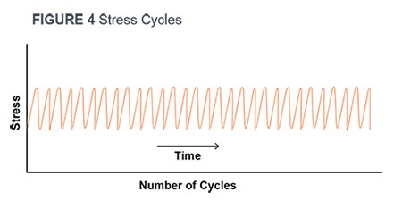
First bars are tested at high stress so failure occurs relatively quickly. Succeeding bars are tested at lower and lower stress until the number of cycles reach 10 million. Most pressure vessel steels are considered to have infinite life at the stress level at which the number of cycles reach 10 million. It should be noted there is considerable scatter in data, with scatter increasing as the number of cycles to failure increases. Stress vs. number of cycles curve (S-N curve) is generated from test data (see Fig. 3). It is common practice to reduce stress by a factor of 2 or number of cycles by a factor of 20, whichever is more conservative when generating the S-N curves for design purposes. Reduction factors used for S-N curves cover scatter in the data, environmental effects, and size effects.
A number of conditions affect fatigue life of a pressure vessel. Some conditions listed below have a greater effect on fatigue life than others, but all affect fatigue life of vessels in some manner.
- Cyclic stress state: number of stress cycles and the stress range
- Geometry: sharp corners, small radii, and small fillets decrease fatigue life of a vessel component
- Surface quality: polished surfaces increase fatigue life compared to non-polished surfaces
- Weld quality: any defect in a weld decreases fatigue life. Weld surfaces are machined to increase fatigue life of a part
- Material type: some materials are more fatigue tolerant than others
- Residual stresses: stresses resulting from the manufacturing processes such as forming, welding, etc., decrease fatigue life
- Size and distribution of internal defects: inclusions such as sulfides in steel decrease fatigue life
- Grain size: fine-grain steels are more fatigue-tolerant than coarse-grain steels
- Environment: a corrosive environment decreases fatigue life
- Temperature: extreme high and low temperatures decrease fatigue life
Review of the preceding list indicates any design feature or fabrication process that increases stresses, either globally or locally, in a pressure vessel may decrease the fatigue life of the vessel. Vessel design begins with selection of a fatigue-tolerant material, if possible. Features that minimize stresses in vessel are incorporated into the design. Sharp corners are eliminated, large radii are used in place of small radii, and transitions from one geometric shape to another are made as gradual as possible. If stresses are low enough, vessel life can be considered infinite. Vessel design is considered preliminary until completion of fatigue analysis.
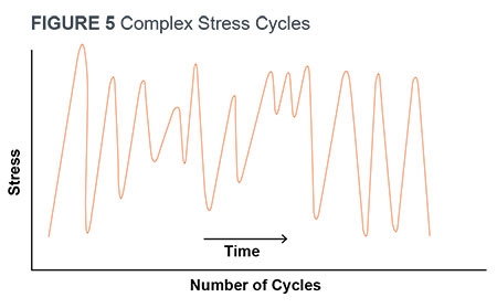
Assume a simple case of a single fluctuating load on a pressure vessel with an equivalent stress amplitude of 250,000 psi for 30 cycles (see Fig. 4). From the S-N curve (Fig. 3), the number of cycles before failure at that stress level is 40 cycles, which exceeds the specified number of cycles, indicating the design is acceptable for the specified fatigue service.
In reality, pressure vessels are subjected to varying pressures, temperatures, and external loads. The user of a pressure vessel specifies all operating conditions and cyclic events to be considered in design of the vessel. A load histogram is prepared from information contained in the user’s design specifications.
From the load histogram, total equivalent stress amplitude at a location is calculated. Total equivalent stress amplitude is defined as one-half of the total equivalent stress range per Section VIII, Division 2. The equivalent stress range is the sum of the average stress across the solid section, bending stress in the solid section, stress at a structural discontinuity, thermal expansion stress, and stress from notches. Equivalent stress is calculated for each set of loads defined on the load histogram. Number of cycles specified for each equivalent stress is compared to number of cycles shown on the S-N curve for that stress. If the number of permissible cycles from the S-N curve is greater than the number of specified cycles, the vessel design is acceptable.
The stress induced in a pressure vessel shell as pressure goes from atmospheric to operating pressure and back to ambient pressure is one stress cycle. Between increasing and decreasing pressure may be many pressure fluctuations (see Fig. 5). Stresses associated with pressure fluctuations and number of cycles must be determined. As complexity of loadings on the vessel increases, difficulty of counting stress cycles increases and becomes increasingly onerous. Rainflow counting algorithm, or other methods complying with ASTM E1049, Standard Practices for Cycle Counting in Fatigue Analysis, is used to count stress cycles and combine partial cycles into complete cycles.
There are multiple stress cycles with different stress magnitudes and associated number of cycles. Fatigue damage from each stress cycle is cumulative, and the effect of all stress cycles must be determined. Miner’s rule is used to evaluate effects of all stress cycles on vessel fatigue life. Miner’s rule:
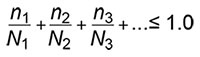
Where n1 is the number of specified cycles at stress level 1, n2 is the number of specified cycles at stress level 2, and n3 is the number of specified cycles at stress level 3, and so on. N1 is the number of permitted cycles at stress level 1, N2 is the number of permitted cycles at stress level 2, and N3 is the number of permitted cycles at stress level 3, and so on. If the sum of the ratios is less than or equal to 1.0, vessel design is acceptable for that point in the vessel. This process must be repeated at other points in the vessel where there are high stresses. Vessel design is acceptable when all points in the vessel satisfy Miner’s rule.
Actual life of a pressure vessel may or may not exceed the predicted life. If vessel operating loads are less than loads used in fatigue analysis it is probable vessel life will exceed loads used to predict vessel life. Conversely, if operating loads exceed predicted life it is probable the actual life will be less than the predicted life. An actual end of life date cannot be defined with a high degree of certainty.
Pressure vessels should be visually examined on a regular basis throughout their lives for impact marks, scrapes, corrosion, erosion, wear, cracks; anything that changes internal and/or external surfaces of vessels. Each finding should be evaluated for its effect on fatigue life of the vessel. For example, pitting corrosion can greatly increase local stresses and dramatically decrease fatigue life of the vessel. It is good practice to thoroughly examine by visual and appropriate Non-Destructive Examination (NDE) methods the interior and exterior surfaces of the vessel when it has reached 50% of its predicted life. Results of this half-life examination are used to determine if the vessel is in condition for operation to predicted end of life, or to revise predicted end of life.
As the vessel approaches predicted end of life, visual examination should be supplemented by other NDE methods in search for cracks in highly stressed areas of the vessel. The effect of any crack on fatigue life should be evaluated immediately as failure may be imminent. Failure may be a slow leak or may be catastrophic.
Regular examinations of vessels should be part of a plan to either replace the vessel at end of life, or to extend its life past its calculated fatigue life. A complete detailed history of the vessel is required to extend vessel life. History should include actual pressures and temperatures, inspection reports, etc. Actual operating loads may not have been of the magnitude used for fatigue analysis. It may be possible to extend vessel life when fatigue analysis is based on actual operating loads.
Obviously, not all parts of a pressure vessel are equally stressed. The most highly stressed areas occur at changes in geometry: nozzles, transitions in diameter, etc. Cracks can be repaired and cracked components replaced. Fatigue analysis of the repair or replaced component is required to ensure vessel life is extended past the original design life. Another alternative is to perform a fitness for service analysis per API(4) 579-1/ASME FSS-1. Fitness for service analysis provides an estimate of number of cycles to failure.
Of course, cost of replacing a vessel versus cost of examination, repairs, and analysis required to extend vessel life is always a consideration. But the planning and record keeping required to have the option to extend vessel life past its predicted life begins with purchase of the vessel.
References:
- ASME. VIII, Division 2 Alternative Rules, Rules For Construction of Pressure Vessels. New York: ASME, 2010.
- Harvey, John F. Theory and Design of Modern Pressure Vessels. New York: Van Norstrand Reinhold Company, 1974.
- *Modified version of ASME. VIII, Division 2 Alternative Rules, Rules For Construction of Pressure Vessels. New York: ASME, 2004 edition with the 2006 addendum.
- American Petroleum Institute