Paper Machine Failure Investigation: Inspection Requirements Should Be Changed For Dryer Can
James E. Bennett
Engineering consultant, La Grange, TX
59th General Meeting in 1990
Category: Operations
Summary: The following article is a part of National Board Classic Series and it was published in the National Board BULLETIN. (9 printed pages)
The following material represents the author only and should not be assumed to be the opinion or policy of The National Board of Boiler and Pressure Vessel Inspectors or The American Society of Mechanical Engineers administration, staff, or membership unless so acknowledged.
Abstract
In April 1989, four dryer cans in a vintage paper machine manufactured about 1914 by Pusey Jones Corporation failed. The investigation of the accident determined that the root cause of the failure was a torsional fatigue crack that initiated on the OD surface of one of the cans. Subsequent inspection located a similar crack about 5" long in another can that had penetrated 3/4 of the can shell as well as numerous small defects with the same orientation. These major cracks were located outside of the "high stress areas" associated with the heads typically specified for periodic inspection. Based on this failure, it is recommended that, at least for old machines, 100 percent wet fluorescent magnetic particle inspection of the can shell OD surface be included in the inspection requirements.
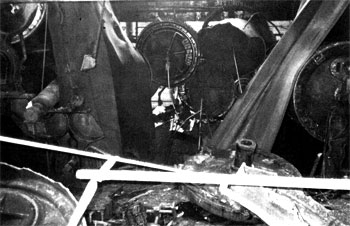
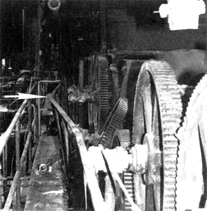
As shown in Figure 1, the explosive force of this failure scattered debris around the machine and left the drive gear sections, Figure 2, hanging in the support structure. Due to the serious nature of the accident, the company wanted an independent laboratory rather than its corporate laboratory to investigate the failure. Metallurgical Services Company of Kentucky, Inc., arrived at the site before any of the failed parts, except for those on the floor that interfered with the operation of the adjacent machine, were moved. A plan was presented for the orderly removal and identification of all parts from the dryer cans and support structure involved in the accident.
FIGURE 1: General View of Tend Side of Paper Machine Showing
Debris on Floor After Accident.
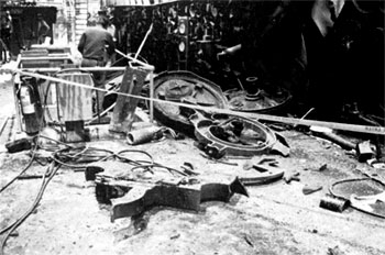
FIGURE 2: General View of Damaged Portion of Paper Machine
Showing Drive Heads and Gears Hanging in Support Structure.
The first part of the investigation separated the tend and drive side support structure parts. These parts were reassembled into their approximate original position as shown in Figure 3.
FIGURE 3: General View of Tend Side Support Structure After
Pieces Were Assembled into Original Positions.
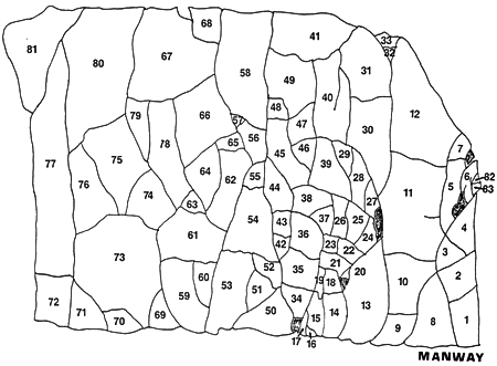
The four failed dryer cans, identified as numbers 13, 14, 15 and 16, broke into many pieces during the accident and were mixed together in the basement area under the machine. All of these pieces had to be sorted and pieced together as part of the effort to identify the initiation area for the failure. As you can imagine, this was a formidable task but we were able to reassemble three of the cans completely to duplicate a typical can shown in Figure 4. The fourth can broke into many small, similarly shaped pieces, so only sections of this can could be reassembled. After the cans were reassembled, all of the pieces were numbered (Figure 5) to identify each piece during nondestructive inspection and fracture surface examination. Can numbers 13 and 14 had fewer and larger pieces than can number 16. Can number 15 had the highest number of pieces, which also were smaller than the pieces of the other cans.
FIGURE 4: View of Dryer Can Pieces Reassembled into
Approximate Original Position.
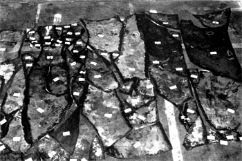
FIGURE 5: Typical Sketch of Dryer Can Pieces Showing
Numbers Used to Identify Pieces.
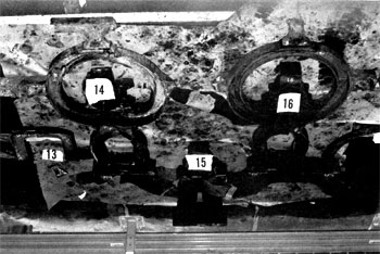
After all of the parts were properly positioned and identified, the investigation proceeded to locate the origin and cause of the accident. Examination of the tend side support structure found that the support for one side of dryer can number 16 was twisted as shown in Figure 6. On the drive side, the guardrail along the walkway, Figure 7, was bent in line with dryer can number 16. It also had a fresh cut mark indicating contact with the gear. These findings indicated dryer can number 16 initiated the accident.
FIGURE 6: Close-Up View of Support Under One Side of Can #16
Showing Movement Relative to Base. Note Difference in Space at Arrows.
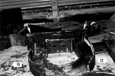
FIGURE 7: General View of Drive Side Showing Damage to
Guardrail (Arrow) Along Walkway at Can #16 Location.
The OD surface of all of the dryer can pieces were liquid penetrant inspected. There were few defect indications on the pieces from can 13 and 14. Can 15 pieces had more defect indications than cans 13 and 14 but there was no apparent concentration of the indications in a particular area. In contrast, can 16 had many indications and, as shown in Figure 8, they were concentrated in two areas. Figure 9 is a typical view of the defect indications in these areas. The defect indications in pieces 13, 22, 24, 25 and 26 were in a helical direction relative to the longitudinal axis of the can, whereas the others tended to be in the longitudinal direction. Examination of crack surfaces associated with the helical indications found thumbnail striations of a fatigue crack.
FIGURE 8: Sketch of Dryer Can #16 Showing Location of
Liquid Penetrant Defect Indications on OD Surface.
(Arrow Pointing to Piece 24 to Show Initiation Site of Accident.)
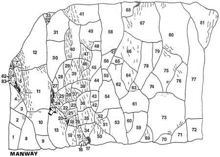
FIGURE 9: Typical View of Liquid Penetrant Indications
on OD Surface of Dryer Cans After Accident.
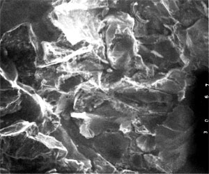
A large number of fracture surfaces were cleaned and examined using an optical stereomicroscope. One fracture area, Figure 10, contained a series of fatigue striations initiating at the OD surface and progressing to the ID surface. This fracture was about 6" long, located about 3' from the tend end, and oriented about 35° from the longitudinal axis of the can. The features of this fracture, Figure 11, were rounded, indicating an "old" crack. All of the other fractures had sharper features which are typical for a "new" crack, with a typical area shown in Figure 12. Thus, it was concluded that dryer can 16 was the initiation point for the accident at this location.
FIGURE 10: Photograph Showing Fatigue Striations (Arrows)
on Can #16 Fracture Surface with OD Surface at Top Edge.

FIGURE 11: Scanning Electron Microscope View of Fracture Surface Shown in Figure 10.
Note Rounded, Smooth Features of Surface. (300X)
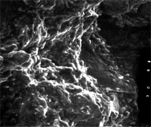
FIGURE 12: Scanning Electron Microscope View of Fracture Surface Typical of All Others Examined.
Note Sharp, Well-Defined Features of Surface. (300X)
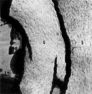
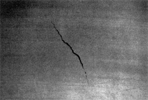
During the investigation of this accident, a complete nondestructive inspection was performed on the remaining dryer cans in the machine. This inspection found many areas with clusters of small indications oriented at an angle to the longitudinal axis of the dryer can. One can had a 5" long indication, Figure 13, at the same location and orientation as that identified as the initiation point of the accident. Examination of the surface of this crack found striations and rounded features similar to those in the initial crack, and they had progressed to a depth of 3/4 of shell thickness.
FIGURE 13: General View of 5" Long Crack Found in Can #6
at Same Location Where Failure Initiated in Can #16.
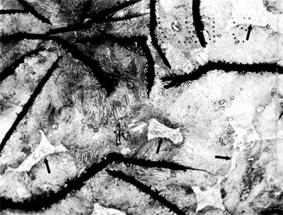
Analysis of the dryer can material found it to be a typical gray cast iron composition except for a higher phosphorus content (0.75 percent) than normally used today. At the time these dryers were manufactured, it was added to improve fluidity of the metal. The microstructure, Figure 14, was typical for gray iron castings with a steadite phase as expected with the high phosphorus content. The mechanical properties varied from a low of 10,500 psi in one can to a high of 17,600 psi in another.
FIGURE 14: Typical Microstructure of Dryer Can Shell Material.
Arrows Point to Steadite Phase.
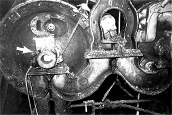
As stated previously, this investigation concluded that can number 16 initiated the paper machine accident. The location, orientation, and features of the pre-existing crack indicate it was a fatigue crack that developed due to torsional loading. Friction in the tend side bushing, Figure 15, resists the drive side loading and produces a constant twisting load on the can. Start/stop cycles of the machine, as well as paper breaks and rethreading, induce cyclic loading in the can.
FIGURE 15: General View of Dryer Can Support Point Showing
Oil Rag Box for Bushing on Can Shaft.
What does all of this have to do with changes to dryer can inspection requirements? This failure and the second crack detected that both initiated on the OD surface about 3' from one end of the dryer can. These major cracks were located outside of the "high stress areas" associated with the heads typically specified for periodic inspection. Based on this accident, it is recommended that, at least for old machines with bushings instead of bearings, 100 percent wet fluorescent magnetic particle inspection of the can shell OD surface be included in the inspection requirements.
Editor's note: Some ASME Boiler and Pressure Vessel Code requirements may have changed because of advances in material technology and/or actual experience. The reader is cautioned to refer to the latest edition of the ASME Boiler and Pressure Vessel Code for current requirements.