How to Destroy a Boiler -- Part 2
William L. Reeves, P.E
President, ESI Inc. of Tennessee
Category: Incidents
Summary: The following article is a part of the National Board Technical Series. This article was originally published in the Summer 1999 National Board BULLETIN. (7 printed pages)
The second article of a three-part series describing some potentially catastrophic events that power and recovery boilers are prone to if not properly maintained.
IMPACT DAMAGE TO TUBES
When you take a look at a boiler under construction, it is clear that all parts are not created equal. This is particularly true with the boiler tubes that make up the furnace and convection sections. Just as a chain is no stronger than its weakest link, the failure of a single tube with a value of only a few hundred dollars can easily require the shutdown of a multimillion dollar boiler facility.
When you consider that the tube thickness for the pressures commonly associated with many industrial boiler plants is often 0.120", 0.095", or less, it is easy to visualize how easily these tubes can be damaged.
Common Causes of Tube Damage
Impact the tube with a sharp object - The tube material is fairly soft and even a cold chisel dropped from a few feet away can result in a gouge and a localized thin spot on the tube. Any added stress can cause the unit to fail when it is pressurized and can also serve as a point of concentrated corrosion. This type of damage is common when boiler convection sections are mechanically cleaned of hard buildups, or when refractory repairs or repairs to other tubes are made. The simple drop of a hand tool can result in thousands of dollars in repairs as well as potential downtime of the unit.
Sootblower alignment - Sootblowers use high velocity jets of steam to blow the soot from the tubes. One of the pre-start-up checklist items for any boiler should be to verify the proper orientation and alignment of the sootblower lance to insure that the jets are blowing between the tubes and not blowing directly on the tubes during sootblower operation. Sootblower alignment is done when the unit is cold. Therefore, when aligning the sootblower lance, the thermal expansion of both the boiler and the sootblower lance must be taken into consideration.
Sootblowing with wet steam - Although a direct jet of steam striking the tubes as a result of out-of-alignment sootblowers is bad enough, the damage is compounded if wet steam is utilized. A direct blast of high pressure condensate can quickly cut through the thin tube surfaces, resulting in tube failure. The most common cause of wet steam is inadequate warm-up and draining of the sootblower lines. Proper sootblowing techniques require that the entire steam line supplying steam to the sootblowers be preheated to remove all condensate from the lines.
Corrosion - Fireside corrosion damage often occurs on a boiler that is in cold standby and that has previously fired sulfur-laden fuels. There are, inevitably, areas of the boiler where ash is not removed from the tube surface during normal sootblower operation. One of the most vulnerable areas is the interface where the tubes enter the drum at tube-baffle interfaces and refractory-to-tube interfaces. When the boiler is hot, corrosion is generally not a problem since moisture is not present; however, upon shutdown, this ash and refractory can absorb moisture and concentrated corrosive attack will occur over time in these areas. This will commonly cause boilers, which are subject to extensive periods of cold storage, to be damaged to the point that retubing is necessary. Localized pitting can be quite deep, rendering an otherwise sound tube in need of at least partial replacement.
Preventive Measures
- Make sure that all personnel who interact with boilers understand that thin tubes are quite fragile. Encourage workers to report any accidental damage so that it can be inspected or repaired as necessary.
- When possible, store a standby boiler in a hot condition to prevent fireside corrosion of the tubes.
- Hot storage techniques, such as utilizing mud drum heaters or routing the blowdown from an operating boiler through the inactive unit, are generally sufficient in keeping the temperatures of the tubes above the corrosion dew point.
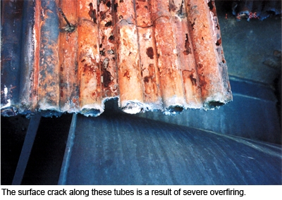
SEVERE OVERFIRING
One doesn't have to spend much time in manufacturing plants to realize that maximizing production availability and output are some keys to profitability. This mindset requires that every piece of equipment be pushed to its maximum capability right up to the point of its self-limits or failure. Most equipment simply will not run any faster or produce any more product due to physical limitations.
The operation of steam boilers beyond their Maximum Continuous Rated (MCR) capacity has long been an issue of heated discussion. For many years, boiler manufacturers have rated their equipment to have a specific MCR on a continuous operating basis with a two- to four-hour peak rating, often times at 110 percent of MCR. The $64,000 question that is always raised is, "If the boiler will operate at 110 percent of MCR for 4 hours, why can't it operate at 110 percent continuously?" The answer to this good question is complex and is somewhat like trying to answer the question, "How high is high?"
In the design of a steam generating system, margins are built into the peripheral equipment of the boiler to ensure the capability of meeting performance guarantees. These margins include such items as additional fan volume and static capability, pump capacity and TDH (Total Discharge Head) margins, oversized material handling systems to accommodate operating logistics, etc. Any good designer/builder of steam generating systems wants to ensure that no piece of auxiliary equipment is the limiting factor to the boiler producing the MCR, or peak capacity, using the worse case contract fuels. Typically, the conservative design of all equipment results in the capability of overfiring the boiler above and beyond the peak 110% MCR rating. Without the self-limiting capability of the auxiliary equipment, management demands put upon steam plant superintendents to maximize production often result in continuous and sometimes severe overfiring of the equipment.
Sometimes the physical limitations of the boiler, such as furnace size or steam piping, will cause sudden and dramatic problems such as emissions or pressure drop problems that limit the boiler operating capacity. However, other physical limitations of the boiler itself may not be so obvious. These limitations lead to other problems associated with severe overfiring, which may include:
- short- or long-term overheating damage to refractory, tube metallurgy, breeching, etc.;
- long-term erosion of boiler tubes, baffles, breeching, and particulate clean-up devices;
- long-term corrosion of furnace wall and superheater tubes; and
- steam moisture and solids carryover causing problems with superheater tubes, steam turbine blades, and other process equipment.
Certainly, the fuels being fired have a dramatic effect upon the potential problems associated with severe overfiring in the list above. Erosion problems are typically associated with firing solid fuels such as coal, wood, sludge, plant waste, etc., that have ash and particulate constituents. The overfiring condition increases the gas weights and velocities which have a square function relationship to pressure drop and the effects of erosion. Severe eddy effects can be generated in boiler back passes that result in dramatic localized erosion problems.
Boiler designers carefully consider the heat flux through furnace wall tubing and membrane as well as the surface operating temperatures of tube walls, refractory, etc. Overfiring the furnace results in higher heat flux through the furnace walls and higher surface temperature of the refractory. The total steam flow relates to certain downcomer flows and pressure drops to ensure adequate cooling of furnace wall panels, etc. Overfiring the boiler results in higher flow rate demands in downcomer circuits which raises the pressure drop, thus impeding flow. The combination of these two conditions can result in a substantial increase in the tube and membrane operating temperatures. The short- and long-term effects of running at higher temperatures can result in the degradation of the tube metallurgy and strength.
Corrosion problems can be compounded when undesirable compounds in oil and solid fuels come in contact with tubes operating at higher operating temperatures. Also, overfiring oil burners can result in flame impingement on furnace wall tubing, resulting in localized corrosion.
In summary, most well-designed steam generating equipment is capable of being operated above MCR. Operating peripheral equipment at their physical limits does not often create problems. Conversely, operating the steam generator continuously above MCR may cause long-term maintenance problems resulting in associated costs that are not easily detectable during the short term. In situations where the production demand warrants overfiring the steam generating equipment, it may be a good business decision to suffer the short- and long-term increased maintenance costs to get the extra production.
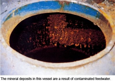
CONTAMINATED FEEDWATER
Contaminated feedwater, which is a combination of both make-up and condensate returns, is a complex issue in this three-part series. Entire books have been written on this subject and its effects. This article will only try to create an awareness of some common problems. Common feedwater contaminants include:
- Oxygen
- Excessive boiler treatment chemicals
- Oils
- Miscellaneous metals and chemical compounds
- Resin
Dissolved oxygen is a common and constant threat to boiler tube integrity. The use of modern, sophisticated chelant water treatment programs has dramatically improved the cleanliness of boiler heat transfer surfaces to such an extent that essentially bare-metal conditions exist. Since only a thin magnetic oxide film remains on boiler metal surfaces, oxygen control is extremely important. The typical boiler plant is equipped with a deaerating feedwater heater to remove the majority of oxygen. In boilers operating below 1,000 psig, the oxygen scavenger, sodium sulfite, is continuously fed to the storage tank of the deaerator and the scavenger is necessary to ensure the absence of free oxygen.
One of the most serious types of oxygen corrosion is oxygen pitting, which is the concentrated pitting and corrosion of a very small area. A tube failure can occur even though only a relatively small amount of corrosion and loss of metal has been experienced. Because of the rapid and catastrophic effects of oxygen corrosion, boiler feedwater should be checked periodically to ensure that the deaerating heater and oxygen scavenger are eliminating free oxygen in the boiler feedwater.
A chelant boiler water treatment program that is not properly maintained to ensure proper dosages of chelating chemicals can result in problems with the consequences that these chemicals are intended to prevent. Chelant corrosion or attack develops only when excess concentrations of sodium salt is maintained many times above the control level over a period of many months. The resultant attack is a dissolving or thinning of metal, unlike oxygen pitting. The attack concentrates on areas of stress within the boiler such as: rolled tube ends, baffle edges, tube welds, threaded members, and other non-stress relieved areas. Here again, proper monitoring of the boiler water treatment program dosages and residuals can prevent this type of problem.
The inadvertent introduction of acid and caustic can cause the most devastating immediate damage to a boiler. The presence of either of these chemicals can cause a multitude of different types of corrosion and destruction of metal integrity. These chemicals are commonly unintentionally introduced into a boiler for the following reasons:
- Equipment failure or malfunction - A typical problem might be leaking regenerant isolation valves or failure of an automatic controller that results in an inadequate rinse cycle.
- Poor water treatment system design - Double block and bleed valve systems should be used wherever any regenerant chemicals are introduced into the water system to protect against damage due to valve failure.
- Poor water treatment system training and operations - If operators are not properly trained and cognizant of the importance of operating these often sophisticated systems properly, they could be responsible for pumping concentrated acid and caustic into the boiler. A less likely problem might be improperly carrying out the regeneration of water treating equipment such as improper rinsing of residual acid and caustic.
When operating a demineralized water treatment system, the importance of proper maintenance and operator training to prevent these types of catastrophic events cannot be overemphasized.
The undetected contamination of condensate returns is another common problem that leads to boiler feedwater contamination. Contaminants can vary from metals such as copper and iron to oils and process chemicals. Heavy metal contamination is usually a function of the construction materials of the process equipment and the condensate system. Oils and process chemicals are generally introduced into the condensate system due to process equipment failures or corrosion-caused leaks in equipment such as heat exchangers, pump and gland seals, etc. The biggest risk associated with condensate system contamination is a catastrophic failure of a piece of process equipment, which results in the introduction of significant quantities of undesirable chemicals or compounds into the boiler. For this reason, prudent boiler operations should include continuous monitoring of the quality of condensate being returned from the process.
Another problem that sometimes causes severe boiler fouling is the introduction of ion exchange resin into the boiler feedwater system. This is frequently caused by the failure of the ion exchange vessel internal piping or lateral screens. Depending upon the operating pressure of the boiler and type of resin, this problem can result in a severe coating of resin material on boiler surfaces. An inexpensive and very worthwhile method to alleviate the chance of this type of contamination is to install a resin trap on the outlet of any ion exchange vessel. Resin traps not only protect the boiler from contamination, but they also prevent the loss of very expensive resin in the event of a failure.
Boiler feedwater contamination can be a slow, degenerative process or an instantaneous, catastrophic event. Routine and efficient maintenance procedures will greatly mitigate the chances of both types of occurrences. Consistent boiler water and feedwater quality monitoring and testing provides operating personnel not only with historical data, but also with timely warning any time feedwater quality changes dramatically.
Editor's note: Some ASME Boiler and Pressure Vessel Code requirements may have changed because of advances in material technology and/or actual experience. The reader is cautioned to refer to the latest edition of the ASME Boiler and Pressure Vessel Code for current requirements.