System Design, Specifications, Operation, and Inspection of Deaerators
Robert J. Beckwith
Joseph 0. Sawtell
Harold A. Stokes
Strati Yorgiadist*
April 1988
Category: Operations
Summary: The following article is a part of National Board Classic Series and it was published in the National Board BULLETIN. (7 printed pages)
Deaerator cracking can be controlled by periodic inspection and repair of operating units.
Catastrophic failure of deaerator pressure vessel welds has included incidents that resulted in plant personnel fatalities. Failures originated as cracks caused by residual, thermal, static, and dynamic stresses, with growth of the cracks accelerated by corrosion fatigue. Weld deformities and hardened material in the heat-affected zone of welds further contributed to these failures. In some instances shell cracking has resulted in small leaks; in others, complete failure has occurred. In response to the life-taking and life-threatening failures reported in 1982 and 1983, technical advisories and guidelines were prepared outlining the necessity of internal weld inspection and recommending methods for inspection and repair. Advisory statements of this type were issued by TAPPI, the National Association of Corrosion Engineers (NACE), and The National Board of Boiler and Pressure Vessel Inspectors. TAPPI and NACE formed advisory groups to address the cracking problem. The TAPPI group is an ad hoc committee of the Steam and Power Committee. NACE established Task Group T-7H-7, Deaerator Cracking, to study and compile information on the subject. The summary of the TAPPI committee 's findings is presented here.
A large number of deaerators have now been inspected. Cracking has been more prevalent than first suspected, appearing in 30 - 50 percent of all industrial deaerators that have been inspected. Cracks have appeared in circumferential and longitudinal weld seams of both the heater and storage vessels. Circumferential seams are susceptible to cracking more than longitudinal seams, with the highest incidence occurring in the 'T' junction of the two seams. Cracks have also appeared randomly at different service nozzle welds affected by thermal expansion and thermal shock.
Cracks are thought to be caused by residual stresses imposed during manufacture, along with thermal and dynamic shock and stress loads imposed during uneven deaerator operation. New evidence suggests that some cracks may originate in the area of pits caused by corrosion. Once cracks begin, they are stressed open during periods of operation, allowing iron oxide to collect on newly fractured surfaces, which causes corrosion fatigue. The slightly hardened heat-affected zone of the weld is where most cracks occur. Therein lies the whole problem corrosion and weld discontinuities followed by cracking and corrosion fatigue along the heat-affected zone of the welded joint.
Inspection and repair is the tool for the control of the growth of cracks. All deaerators, including those vessels designated as ASME constructed and those designated as non-ASME constructed, should be periodically inspected. Inspection, or the inspection supervision, should be conducted by a certified ASNT SNT-TC-1A Level II inspector. After a deaerator is first put into service, it should be inspected within one to two years. After that, the following frequency of inspectionsa was suggested at the NACE 1986 conference:
- Repaired cracks, 1 year or less
- Nonrepaired cracks, 1 - 2 years
- No cracks/no repairs, 3 - 5 years
Repaired vessels, at the same operating conditions, tend to recrack faster than the original vessel. Inspections therefore should be more frequent after repairs.
Table 1. Example of estimated costs for x-ray examination.
| Type of examination |
Explanation |
Estimated cost per tank |
| Spot |
One X-ray shot in every 50 ft of weld, at a circumferential and longitudinal junction. |
$165.00 |
| Postal |
Two X-ray shots in every 50 ft of weld. one at a circumferential and longitudinal Junction and one at random. |
$420.00 |
| 100% |
One X-ray shot per ft of weld seam. |
$4050.00 |
| The tank in which these estimates are based is 8 ft in diameter and 20 ft long. There is a total of 95 ft of weld in three circumferential welds, and two longitudinal welds. |
A major part of any inspection program is planning and preparation. The downtime for inspection and repairs is shortened by reducing unforeseen delays. Preparation should include several important steps. First, a data file should be established for each deaerator, including system design drawings, tank modification records, histories of inspections and findings, drawings or sketches showing areas of cracks and repairs, and ASME Manufacturer's Data Reports. Second, a planning meeting should be conducted with the owner, the insurance inspector (an authorized inspector who holds a valid National Board Commission), and qualified inspection and repair team representatives. A schedule for each task, including shutdown and cool time, should be prepared.
The inspection of internal tank and weld seams should include circumferential, longitudinal, nozzle, and other welds affected by residual and operating stresses. The actual nondestructive examination should be in accordance with ASME requirements and NACE guidelines and must be conducted from inside the vessels. Each weld should be prepared and treated by taking the following steps:
- Clean the weld to the base metal (brush, wipe down, etc.).
- Inspect visually, especially at the intersections of circumferential and longitudinal seams.
- Test by the wet fluorescent magnetic particle (WFMP) procedure over the entire weld, in "as welded" condition.
- If cracks are found, grind approximately 20 percent of each weld having cracks flush to the parent metal and retest with WFMP.
- If cracks are found after retesting with WFMP, they must be ground out. Cracks then should be classified as (a) Class I, in which the depth of the crack does not exceed the corrosion allowance, (b) Class II, in which the depth exceeds the corrosion allowance but not the minimum design thickness, or (c) Class III, in which the depth exceeds the minimum design thickness.
- It is mandatory to repair Class III cracks. Repairs must conform to the original design, and field repairs must be acceptable to the authorized (insurance company) inspector.b The repair paperwork should be filed with the owner's records of the vessel.
- Summarize the inspection and repair results in the data file for each deaerator.
The deaerator specification is the most important tool available to improve the construction of new installations by reducing stress and corrosion causes of cracking. The areas of concern are weld joints and attachments affected by:
- Quality of the weld
- Residual stresses of manufacture
- Thermal shock or stress
- Dynamic loads imposed by operation
- Corrosion.
The quality of welds
An important means of reducing corrosion and stress in weld seams is to ensure that the original weld has good quality. The best way to check weld quality is by X-ray examination. While the cost of X-ray examination will vary from one location to another and from one manufacturer to another, the inspection adds a little to the cost of the deaerator. A comparison of costs for varying degrees of X-ray examination is shown in Table I. Based on the relatively small cost, it is recommended that partial X-ray examinationsc be specified as a minimum for new deaerators.
Residual stresses of manufacture
Cuts of parent metal at weld junctions should be smooth with no torch cuts allowed.
Removal of residual stresses of manufacture is recommended through post-weld heat treatment (PWHT) at a temperature of 1100- 1200oF for a time based on plate thickness as recommended by the ASME Code. If internals could become sensitized to the point of reducing their corrosion resistance, they should be removed. It will be necessary to leave one head off the heater vessel to do this when the head is welded to the vessel, a local PWHT which extends 360o F around the circumference of the vessel must be applied to this last circumferential weld.
Thermal stress and shock loads
Internal components must not impart stress loads to the pressure vessel as a result of differences in thermal expansion. Shell temperature should be uniform over the entire vessel. Cold spots should be avoided. Avoid nozzle welds that will be affected by temperature cycles. Sleeves are an alternative. The deaerator should be specified to accommodate expected forces and moments imposed by piping on all connections.
Dynamic loads of operation
The major forces imposed on a deaerator are caused by pressure changes in a short, limited time. Independent supports should be used between the heating vessel and the storage vessel, designed to avoid additional stress to the interconnecting nozzles.
Specify the manholes be reinforced to distribute load at the shell weld area. Reinforce relief valve nozzles to distribute the valve thrust load at the weld no matter which direction the valve is mounted.
Consider a third fixed center support for long, small-diameter vessels to reduce thermal expansion to 50 percent in each longitudinal direction. This support will also support the load of the centrally mounted heating vessel, with minimum deflection in the storage vessel shell.
Deaerator pressure vessels should have the same design pressure as the header pressure of the steam supply header. This will prevent over-pressure during the steam pressure reducing valve failure in the open position.
Corrosion
Corrosion must be eliminated to the greatest possible extent. Specify a minimum of 1/16-in. corrosion allowance. Design for full vacuum to eliminate vacuum breakers, which allow oxygen to be drawn into vessels during swings in vacuum load. Specify that spray devices be in a vertical position and that they be mounted on a flat surface to prevent leakage.
Internal tray packing and piping devices should be securely fastened so as not to become dislodged. All interconnecting piping between tanks should be covered by baffles to prevent tray and internal damage during pressure reversals.
Primer paint should be required on the exterior of vessels. Nozzles should be factory sealed with desiccant inside the vessels to prevent internal corrosion during shipment and storage.
The deaerator system should be designed to maintain a constant operating pressure and temperature within the deaerator through all operating ranges. Several design suggestions should be considered.
First, install a pressure-reducing valve in the steam line that feeds the deaerator, with its sensing line inside the deaerator itself. The pressure-reducing valve should be near the deaerator (Fig. 1).
FIGURE 1: Flow scheme showing the feedwater mixing tank and the steam pressure-reducing valve
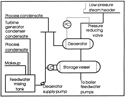
Second, condensates and makeup water should be blended before the deaerator heater. This blending can be done in a piping header just ahead of the deaerator or in a feedwater mixing tank between the demineralizers and deaerator. Blending eliminates the temperature differential between separate makeup water and condensate connections on the deaerator. A feedwater mixing tank has the added advantage of making temperature changes more gradual when condensate conditions vary. The choice should be evaluated based on the relative flows of hot condensate and makeup water, as well as on the history of condensate flow interruptions.
Third, reduce stress on piping connections. Piping design should ensure that actual forces and moments are lower than specified. Steam supply piping should be sloped for condensate to drain to the deaerator.
Fourth, oxygen scavenger should be added in the downcomer between the heater and the storage vessel.
Before operators are assigned to any power plant system, they must understand the intended operating mode. This principle is as true for the deaerator as it is for any other part of the power plant. The deaerator should always be operated as intended by the system designer.
Under normal operating conditions, the deaerator heats water as expected and removes oxygen to an acceptable concentration. In the past, because they have worked so well, deaerators have received little attention. Even if the oxygen removal was less efficient than required, the quantity of oxygen scavenger was simply increased to compensate. Pressure and temperature fluctuations have been considered as normal operating conditions. With the increased attention to improved system design, a corresponding attention to improved operation must follow. The operator should note alarm conditions and monitor all operating data. When any condition fluctuates beyond acceptable limits, especially temperature or pressure, the causes should be found and corrected. Even though abnormal operation of the deaerator may not represent as much of an immediate danger as a low drum level or a safety valve blowing the long-term effect, if not corrected, could be equally catastrophic.
Some abnormal conditions that should be avoided through close operator attention include (a) restricted steam flow, especially with cold feedwater, (b) operation above maximum capacity, (c) operation below minimum effective capacity, (d) operating with blended water temperature too high, (e) any significant pressure or temperature fluctuation, (f) water hammer, and (g) high oxygen in the boiler feedwater from the deaerator.
Deaerator cracking has been found to be widespread, and it has the potential for causing catastrophic failures. The problem can be controlled, however, by periodic inspection and repair of operating units. Good engineering decisions in the specification and design of new deaerators and in the systems in which they operate can eliminate some conditions that could cause cracks to begin and grow. Proper operation of the deaerator is a continuing requirement in avoiding catastrophic failure.
Copyright © 1987 Tappi Journal,. Reprinted with permission from Tappi Journal , July 1987, pp 45-47. Reprinted text has been edited for clarity and space requirements.
*R.J. Beckwith, project engineer, Great Lakes Water Inc., Wales
J.Q Sawtell. senior power specialist, Schuchart & Assoc., Portland, OR
H.A. Stokes, power staff engineer, CRS Sirrine, Greenville, SC
S. Yorgiadis, partner, Sheppard T. Powell Assoc., Baltimore, MD.
a The law of the jurisdiction where the vessel is located may require more frequent inspections.
b The repairs should be completed according to the requirements of the National Board Inspection Code ANSI/NB 23, Chapter III Repairs and Alteration. To assure the total integrity, an organization holding a National Board Certificate of Authorization and the "R" symbol stamp should be used.
c For clarification, the ASME Code, Section VIII, Division 1 did address a condition of "partial radiography." This was deleted and now Section VIII, Division 1 addresses only spot or full radiography.
Editor's note: Some ASME Boiler and Pressure Vessel Code requirements may have changed because of advances in material technology and/or actual experience. The reader is cautioned to refer to the latest edition of the ASME Boiler and Pressure Vessel Code for current requirements.