Steam Traps Affect Boiler Plant Efficiency
Lee Doran
Former National Board Field Staff and International Representative
Category: Design/Fabrication
Summary: The following article is a part of the National Board Technical Series. This article was originally published in the Fall 1997 National Board BULLETIN. (4 printed pages)
A large portion of an inspector's job consists of inspecting steam boiler plants. Buildings that house steam boilers vary from huge electric utility plants to small refinery plants, or commercial businesses such as a bakery or a drycleaner.
During inspections like the ones mentioned above, the inspector is obviously confronted with a variety of situations. Either the inspector will discover a well-maintained boiler plant or, regretfully, a plant that has been neglected or poorly maintained.
In any case, steam or water leakage from a system is always a concern. When a leak occurs there is energy loss, which in turn increases fuel consumption, water treatment cost, and maintenance cost. For example, increased humidity due to leakage contributes to electrical equipment and control failure.
Although obvious leaks are easily found, a big contributor to energy loss could be from a problem not as identifiable: the boiler's steam traps. And depending on the size of the steam plant, a considerable amount of energy loss is at risk if the boiler has faulty traps (see table below). Some larger plants may have 5,000 to 6,000 traps, while small plants may have 100 or less. However, no matter what size plant, a failed steam trap is not always obvious.
Cost of Various Sized Steam Leaks at 100 psi (assuming steam cost $5/1,000 lbs)
| Size of Orifice (in.) |
Lbs Steam Wasted Per Month |
Total Cost Per Month |
Total Cost Per Year |
| 1/2 |
835,000 |
$4,175.00 |
$50,100.00 |
| 7/16 |
637,000 |
3,185.00 |
38,220.00 |
| 3/8 |
470,000 |
2,350.00 |
28,200.00 |
| 5/16 |
325,000 |
1,625.00 |
19,500.00 |
| 1/4 |
210,000 |
1,050.00 |
12,600.00 |
| 3/16 |
117,000 |
585.00 |
7,020.00 |
| 1/8 |
52,500 |
262.50 |
3,150.00 |
The steam loss values assume clean, dry steam flowing through a sharp-edged orifice to atmospheric pressure with no condensate present. Condensate would normally reduce these losses due to the flashing effect when a pressure drop is experienced.
First of all, what is a steam trap? A steam trap is an automatic valve that holds the steam at the load until it gives up its heat energy and condenses to water (condensate). After the steam condenses to water, the steam trap allows only the condensate to pass, thereby contributing to plant efficiency.
Since steam naturally releases heat, which causes condensation, another use for traps is to keep steam lines free of condensate. If the condensate is not removed it will cause water hammer which can cause damage to valves, piping, and equipment. Considerable damage can be costly and eventually require equipment replacement.
Although there are many types of steam traps, the three most commonly used are the inverted bucket steam trap, the float-thermostatic steam trap, and the thermostatic steam trap. A description of all three steam traps follows.
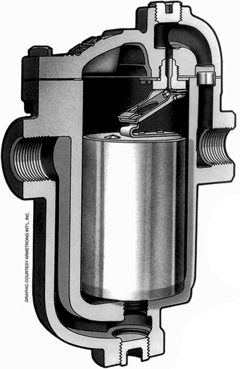
Inverted Bucket Steam Trap
In an inverted bucket steam trap (Figure 1), steam and condensate enter the trap and flow under the bottom of the inverted bucket. As steam collects at the top of the bucket, the bucket rises and closes the discharge valve. As the steam condenses and condensate fills the bucket, the bucket drops down, opening the discharge valve, which allows the condensate to pass. A small hole at the top of the bucket allows air and carbon dioxide (CO2 ) to pass.
FIGURE 1: Inverted Bucket Steam Trap
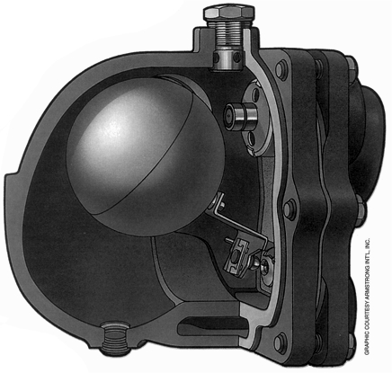
Float Thermostatic Steam Trap
The float thermostatic steam trap (Figure 2 - below) is equipped with a float ball that is connected to the trap discharge valve. As condensate accumulates in the float chamber, it raises the float and opens the discharge valve allowing only condensate to pass. A built-in thermostatic air vent, which discharges air and CO2, is included on this trap. When air and CO2 are present, the air vent opens discharging the elements. After steam at higher temperature is sensed, the air vent closes.
FIGURE 2: Float Thermostatic Steam Trap
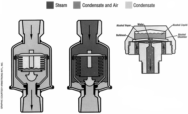
Thermostatic Trap
The thermostatic trap (Figure 3 - below) is equipped with a flexible bellow that expands when steam is present. The bellow closes the discharge valve and traps the steam until it condenses. When cooler condensate is present, the bellow contracts and opens the discharge valve, allowing the condensate to pass. This trap also allows the cooler air and CO2 to pass, causing the bellows to contract.
FIGURE 3: Thermostatic Trap
An inspector may suspect failed steam traps in the system when live steam is being vented into the atmosphere from condensate collection tanks. It is very important not to confuse flash steam with live steam.
What is the difference between live steam and flash steam? Live steam will flow continuously, while flash steam will be intermittent. The inspector must inform the owner/user of the problem and the necessity for corrective action.
At this point, the owner/user is faced with the problem of identifying steam traps that have failed and are wasting energy. To help identify the traps, several techniques can be used:
The Sound Method
To use the sound method, a trained ear is required to detect the sound of live steam passing through the trap. This can be done simply by placing the metal end of a screwdriver on the top of the trap, or near the trap discharge valve, and placing the handle of the screwdriver close to the ear. A stethoscope also may be used. However, this method sometimes may not be practical because of the location of the trap.
The Temperature Differential Method
This method is one of the most acceptable methods for smaller, lower-pressure steam systems. On the smaller systems there are approximately 10 to 20 degrees F differences between the inlet and the outlet of the trap if the trap is functioning properly. In the case of a malfunctioning trap, there would be no temperature differential. Temperature readings can be accomplished by using direct contact thermometers (i.e., strap-on thermometers). Temperature-indicating crayons with specific melting temperatures also may be used, but this method is not accurate and is not recommended for steam traps located in larger plants.
Visual Method
In situations where steam trap maintenance requirements have a high degree of importance, the visual method is another commonly used method to detect failed steam traps. The method is most effective in a location that utilizes a piping arrangement where the trap may be isolated from the condensate system and allowed to drain into the atmosphere. A large plant, possibly housing a large number of malfunctioning traps, is extremely wasteful and very costly to the owner/user. A visual inspection is one method to prevent such costly losses from occurring.
It is recommended that the inspector make an effort to advise the owner/user of the importance of steam trap maintenance and how it increases steam plant efficiency and reduces fuel and maintenance costs.
Editor's note: Some ASME Boiler and Pressure Vessel Code requirements may have changed because of advances in material technology and/or actual experience. The reader is cautioned to refer to the latest edition of the ASME Boiler and Pressure Vessel Code for current requirements.