Basic Weld Inspection - Part 1
John Hoh
Senior Staff Engineer
National Board
Category: Design/Fabrication
Summary: This article was originally published in the Fall 2009 National Board BULLETIN as the first of a two-part series. Please see Basic Weld Inspection - Part 2 for the conclusion of this article.
Note: The purpose of this article is to provide inspectors with a general knowledge of weld inspection. It is by no means intended to compare with the Certified Welding Inspector (CWI) requirements of the American Welding Society (AWS).
Weld inspection begins long before the first welding arc is struck. The inspector must review the job package to become familiar with the:
- welding processes to be used;
- materials and any special properties;
- joint configurations and preparation;
- welding procedure specifications to be used and any limitations;
- qualifications of welders to be used and any limitations;
- heat treatment (pre-heat or postweld), if any;
- nondestructive examination (NDE), if any; and
- specific ASME Code or NBIC requirements (for example, Section VIII, Div. 1, lethal service).
While not imperative, the inspector should learn to read common weld symbols such as the AWS symbols. At the very least, the inspector should always carry a reference guide to interpret weld symbols. Having reviewed all this information in advance, the inspector will be prepared to recognize any problems as they develop rather than after-the-fact.
The following examples and tips are practical applications the inspector can use as a guide.
- The manufacturer or repair organization (certificate holder) has indicated on the job drawing that a weld joint is to be prepared with a 60-degree bevel and root gap of 1/16 inch. Unless the bevels are milled on precision machinery, it is doubtful they will achieve an exact 60-degree bevel as indicated. The easiest solution for the certificate holder is to allow a range of plus or minus a few degrees of the target value. The same holds true for a root gap dimension with no plus or minus tolerance. Even the best welder will have difficulty maintaining an exact root gap dimension. Providing a plus or minus tolerance will make the welder’s job much easier.
- The inspector can use scraps of weld filler wire or rods as a gauge to quickly identify root gaps that are beyond the tolerance range. For example, if the target root gap is 3/32 inch plus or minus 1/32 inch, the inspector should be able to insert a 1/16-inch wire into the gap with little or no resistance. Likewise a 1/8-inch wire should exhibit no side-to-side movement across the gap. Real world situations are rarely this convenient, but the inspector can develop a sense of “too tight” or “too loose” with experience.
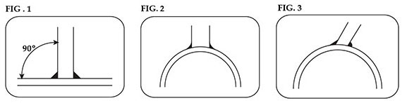
- The certificate holder has designed a simple nozzle to be welded to a flat head (Fig. 1). The nozzle axis is 90° to the flat head, and the attachment weld includes a 3/8-inch fillet weld. The inspector can easily measure the fillet weld to ensure compliance. Now, let’s install the same nozzle in a small diameter vessel shell (Fig. 2). The fillet weld will tend to spread or flatten on opposite sides of the nozzle due to the curvature of the shell. The inspector will need to ensure that the certificate holder has deposited enough weld to meet the design criteria. This example becomes even more critical if the nozzle is installed at an angle other than 90° (Fig. 3).
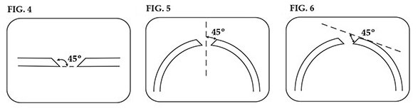
- Using the same nozzle attachment example as described above, let’s look at the weld joint preparation. The certificate holder has specified a 45-degree bevel around the circumference of the hole in the flat head and the vessel shell. Again, the flat head will be very easy to measure, since there is a single plane of reference (Fig. 4). The curved shell will present more of a challenge. The inspector will have to determine if the certificate holder is referencing the bevel from the vertical axis of the nozzle (Fig. 5) or from the variable reference plane of the curved shell (Fig. 6).
- When bevels are prepared with a cutting torch and finished with a grinder, it is very difficult to maintain an exact angle. This is why allowing a plus or minus tolerance is so important. Even obtaining a perfectly circular hole when using a torch and grinder is difficult. Fixtures are available which attach to the torch to aid in cutting circular holes and bevels, but the setup is sometimes inconvenient.
- A certificate holder is preparing to weld several hundred circumferential joints in power boiler tubes. ASME Section I requires these welds to be full penetration, but due to the diameter, thickness, and location in the boiler, radiography of the welds is not required (PW-41, Table PW-11). How does the inspector ensure compliance with the code? Inspectors are trained to believe only what their eyes tell them; but when the inspector cannot see the inner surface of the tube, it becomes difficult to accept that situation. This is when the inspector must take what some would call a “leap of faith.” If the tube ends are properly prepared (beveled) and a qualified welder is using a qualified welding procedure, the odds are very good that the welds will be full penetration. Does this mean the inspector should just accept all this at face value and walk away? Absolutely not! If the inspector is unfamiliar with this certificate holder’s welding procedures and welders, the inspector has the right – and duty – to witness a few of the welds being made to ensure code compliance. One “red flag” to a potential problem would be if the inspector observes that the tube ends have not been beveled. The inspector should immediately ask the certificate holder about this situation. It could be as simple as the certificate holder having just not performed that step in the process yet, or it could be as bad as his or her having tried to save time and money by not beveling the ends. From a practical standpoint, it is extremely difficult, if not impossible, to obtain a full penetration weld when the tube ends are not beveled. The welder would need to start with a large root gap and then be very careful not to “push through” excess filler metal to cause weld build-up on the inside of the tube.