Creep and Creep Failures
David N. French, Sc. D.
President of David N. French, Inc., Metallurgists, Northborough, MA
July 1991
Category: Operations
Summary: The following article is a part of National Board Classic Series and it was published in the National Board BULLETIN. (4 printed pages)
What is creep? Creep may be defined as a time-dependent deformation at elevated temperature and constant stress. It follows, then, that a failure from such a condition is referred to as a creep failure or, occasionally, a stress rupture. The temperature at which creep begins depends on the alloy composition. For the common materials used in superheater and reheater construction, Table I (see below) gives the approximate temperatures for the onset of creep. It should be pointed out that the actual operating stress will, in part, dictate or determine the temperature at which creep begins.
The end of useful service life of the high-temperature components in a boiler (the superheater and reheater tubes and headers, for example) is usually a failure by a creep or stress-rupture mechanism. The root cause may not be elevated temperature, as fuel-ash corrosion or erosion may reduce the wall thickness so that the onset of creep and creep failures occur sooner than expected.
However, regardless of the cause, the failure will exhibit the characteristics of a creep or stress rupture. Indeed, the ASME Boiler and Pressure Vessel Code recognizes creep and creep deformation as high-temperature design limitations and provides allowable stresses for all alloys used in the creep range. One of the criteria used in the determination of these allowable stresses is 1% creep expansion, or deformation, in 100,000 hours of service. Thus, the code recognizes that over the operating life, some creep deformation is likely. And creep failures do display some deformation or tube swelling in the immediate region of the rupture.
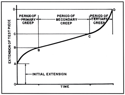
Figure 1. Schematic creep curve. Courtesy Babcock & Wilcox.
At elevated temperatures and stresses, much less than the high-temperature yield stress, metals undergo permanent plastic deformation called creep. Figure 1 shows a schematic creep curve for a constant load; a plot of the change in length verses time. The weight or load on the specimen is held constant for the duration of the test. There are four portions of the curve that are of interest:
- An initial steep rate that is at least partly of elastic origin, from point "0" to point "A" in Figure 1.
- This is followed by a region in which the elongation or deformation rate decreases with time, the so-called transient or primary creep, from region "A" to "B" of Figure 1. The portion from point "0" to point "B" occurs fairly quickly.
- The next portion of the creep curve is the area of engineering interest, where the creep rate is almost constant. The portion from "B" to "C" is nearly linear and predictable. Depending on the load or stress, the time can be very long; two years in a test and several decades in service.
- The fourth portion of the creep curve, beyond the constant-creep-rate or linear region, shows a rapidly increasing creep rate which culminates in failure. Even under constant-load test conditions, the effective stress may actually increase due to the damage that forms within the microstructure.
Without going into a detailed discussion of the atom movements involved in creep deformation, suffice it to say that creep deformation occurs by grain-boundary sliding. That is, adjacent grains or crystals move as a unit relative to each other. Thus, one of the microstructural features of a creep failure is little or no obvious deformation to individual grains along the fracture edge.
The first two stages will not leave any microstructural evidence of creep damage. Somewhere along the linear portion of Figure 1, the first microstructural evidence of damage appears as individual voids or pores. The location of these first voids or holes varies, often noted at the junction of three or more grains, occasionally at nonmetallic inclusions. These individual voids grow and link to form cracks several grains long, and finally failure occurs. The ultimate rupture is by a tensile overload when effective wall thickness is too thin to contain the steam pressure.
Since creep deformation occurs by grain-boundary sliding, the more grain boundary area, the easier creep deformation will be. Creep deformation and creep strength are a grain-size sensitive property. Thus a larger grain size improves creep strength. For austenitic stainless steels, SA213 TP321H for example, the code requires a grain size of #7 or coarser, to assure adequate creep strength. The elevated temperatures where creep occurs lead to other microstructural changes. Creep damage and microstructural degradation occur simultaneously. For carbon steels and carbon-1/2 molybdenum steels, iron carbide will decompose into graphite. For the low-alloy steels of T-11 and T-22, the carbide phase spheroidizes. Thus, creep failures will include the degraded microstructures of graphite or spheroidized carbides along with the grain-boundary voids and cracks characteristic of these high-temperature, long-time failures.
While creep failures are expected for superheaters and reheaters operating at design conditions, deviations from these parameters will promote early failures. The steam temperature always varies some from individual tube to tube, and the design allows for this variability. However, when the range of temperatures is larger than accounted for, the hottest tubes fail sooner than expected. A more likely cause of premature failure is the slow increase in tube-metal temperatures due to the formation of the steam-side scale.
Steam reacts with steel to form iron oxide along the ID surface of the tube.
The microstructures themselves will show the grain-boundary sliding and the resultant creep cracks or voids. For stainless steels, the microstructures are similar in that the failure is by grain-boundary-sliding and crack formation.
In a superheater or reheater tube, often the very first sign of creep damage is longitudinal cracks in the steam-side scale. As creep deformation expands the tube diameter, the brittle ID scale cannot follow the expansion. Cracks develop in an axial or longitudinal direction which is perpendicular to the principle hoop stress. With time, the tube continues to expand, and these cracks widen. This wide crack shortens the path from steam to steel; iron oxide forms preferentially at the tip of the crack, as there is less oxide thickness to protect the steel; and a cusp forms within the steel tube. The cusp acts as a notch or a stress raiser, reducing the local wall thickness. Creep voids form here, often before any other obvious grain-boundary damage appears elsewhere within the microstructure. With continued high-temperature operation, creep cracks grow from the cusp and ultimately weaken the cross section to the point where failure occurs.
Creep failures are characterized by:
- bulging or blisters in the tube
- thick-edged fractures often with very little obvious ductility
- longitudinal "stress cracks" in either or both ID and OD oxide scales
- external or internal oxide-scale thicknesses that suggest higher-than-expected temperatures
- intergranular voids and cracks in the microstructure
Editor's note: Some ASME Boiler and Pressure Vessel Code requirements may have changed because of advances in material technology and/or actual experience. The reader is cautioned to refer to the latest edition and addenda of the ASME Boiler and Pressure Vessel Code for current requirements.
Table I
Initial Creep Temperature
For superheaters and reheaters, the scale that forms is essentially magnetite alloyed with chromium, molybdenum, manganese, and silicon from the alloy steels of T-11 and T-22. For waterwalls, the iron oxide may be contaminated with impurities from the boiler water and corrosion debris from the pre-boiler circuits of condenser and feedwater heaters. In any event, the thermal conductivity of the steamside scale is about 5% of the thermal conductivity of the steel tube. Thus, an effective insulating layer forms and prevents proper cooling of the tube metal by the steam. The net effect of the scale is to raise the tubemetal temperature. Depending on the scale thickness, which is dependent on the time and temperature of operation, tube-metal temperature increases of 25 - 75oF are likely. Such a large increase raises tubemetal temperatures beyond the safe design range. These elevated temperatures result in increased creep deformation rates, more rapid oxidation and corrosion (thinner walls and higher stress) and hasten the onset of creep failures. An increase of 60oF (from 1040oF to 1100oF for example) will decrease creep life by 90%. An increase of 60o F due to steam-side scale formation in a superheater or reheater is not unusual.
| Carbon steel....................... |
800oF |
| Carbon + 1/2 Molybdenum............ |
850oF |
| 1-1/4 Chromium-1/2 Molybdenum...... |
950oF |
| 2-1 /4 Chromium-1 Molybdenum....... |
1000oF |
| Stainless steel.................... |
1050oF |