Real-Time Radioscopic Examination
Richard S. Peugeot
President, Peugeot Technologies Inc.
58th General Meeting in 1989
Category: Operations
Summary: The following article is a part of National Board Classic Series and it was published in the National Board BULLETIN. (9 printed pages)
The following material represents the author only and should not be assumed to be the opinion or policy of The National Board of Boiler and Pressure Vessel Inspectors or the American Society of Mechanical Engineers administration, staff or membership, unless so acknowledged.
Background
On November 8, 1895, Professor Dr. W. C. Roentgen astounded the world with his discovery of X-rays. X-rays were first discovered by fluorescence meaning that radioscopy, or fluoroscopy as it was formerly called, pre-dates film radiographic examination. Yet, radiography is a more widely accepted examination procedure than is radioscopy.
What is the reason for this paradox? Fundamentally, there are two reasons. The first reason is that when a direct comparison is made under similar imaging conditions between the quality of static images on X-ray film and on a real-time display, the film image usually appears to be of higher quality. The second reason is that radioscopy has never been recognized as a different examination modality with its own distinct set of advantages and disadvantages. Fundamentally, radiography is an off-line, static examination technique, while radioscopy is a dynamic examination technique with the potential for on-line examination and process control.
Codes and Standards
Why should codes and standards-writing bodies promote radiography and not real-time radioscopy when both have legitimate roles in the nondestructive examination process? After all, the common goal is to assure a high level of quality and reliability in the manufactured products to which these codes and standards apply. Fortunately, this perception is beginning to change. In 1988, ASTM issued E 1255-88, "Standard Practice for Radioscopic Real-Time Examination." This is the first radioscopy standard with general applicability to a wide range of real-time X-ray examination environments. It anticipated that other codes and standards-writing bodies, including ASME and MIL-STD, will soon produce other radioscopic examination standards [Please see ASME code Section V, Article 3].
Radioscopy has been a per examination technique for many years in certain selected industries with excellent success. For example, the American Petroleum Institute under API-5LX has permitted the use of radioscopic examination in conjunction with film radiography for the examination of continuously welded oil and gas transmission line pipe with excellent success. Many, many other successful radioscopic applications exist for in-house quality control procedures. Yet, these successful in-house examination measures must often be followed by approved radiographic procedures before the product can be "sold." There is nearly universal agreement that radioscopic examination works for many, many applications. As with all nondestructive examination techniques, it is a matter of making a proper application of the technique. There is little difficulty today in making a distinction between the proper application of radiographic and ultrasonic examination techniques because they are recognized as distinctly different NDE techniques. Because we have not yet learned to make the same distinction between radiography and radioscopy, radioscopy is often discounted as a permissible, or even viable, NDE technique. The use of a valuable technique which offers superior flaw-finding capabilities for many kinds of defects is thereby discouraged.
Advantages of Radioscopy
For most applications the pre-examination cost of radioscopy is lower than for radiography. This comes about due to the savings associated with expendable items, such as film and chemistry, as well as labor savings since there is no X-ray film to position, develop, read and store. Other hidden costs associated with radiography include the transportation of the test object to a remote X-ray facility and the delay in receiving the test results.
The highest and best use of any NDE technique is as a process control technique. Through careful control of the manufacturing process many defects can be prevented, rather than merely detected after-the-fact. A realtime technique, such as radioscopy, which presents timely information about the quality of the manufacturing process has the potential to be a process control tool. Off-line testing represents a negative cost of quality and can only increase the scrap rate. On-line process control is a positive cost of quality and can effectively lower the scrap rate.
The continuing use of radiography at the expense of radioscopy is fostered by the very means used to verify the quality of the examination process. The penetrameters and image quality indicators used to evaluate the quality of the radiographic inspection technique are prime examples. These devices favor the static performance characteristics of film radiography and are poor indicators of the ability of the radiography to find actual flaws that are often very orientation sensitive. On the other hand, radioscopy, which is a dynamic technique and can observe the test object in motion through a wide range of viewing angles, is often better at finding critical, orientation-sensitive defects. The question might seriously be asked: "What do you want to see - penetrameters images or defects?"
Radioscopy and Radiography
The purpose of this paper is not to take away from film radiography, but to bring it into balance with radioscopy. Radiography earned its eminent status as a widely-accepted NDE method for entirely valid reasons. Radiography achieves its very high level of stationary imaging performance through the use of high-performance X-ray equipment and X-ray film. Today's state-of-the-art X-ray equipment utilizes rugged, compact and reliable metal ceramic X-ray tubeheads having very small focal spots and low inherent filtration to produce sharp, high-contrast X-ray images. X-ray controls are microprocessor-based and can be digitally linked with other key elements of the radioscopic system. Modern high tension generators use the latest in high stability, low ripple, high voltage generation techniques to produce an accurate, repeatable and highly stable source of X-rays. The same high performance X-ray generation equipment powers both radiographic and radioscopic equipment, so any performance differences between the two must be attributable to the image receptor.
Simply stated, industrial X-ray film presently has no equal in a real-time, large-format electronic X-ray image receptor. One way of relating the static mode performance difference between X-ray film and a real-time radioscopic image display is based upon information content. If the information potential of a sheet of 14" x 17" fine grain X-ray film is compared to a 12" realtime television display operating at 825 scan lines, it can be shown that the X-ray film contains 8.4 billion bits of information, while the real-time image contains only 1.5 million bits of information.1
While such comparisons are meaningful, they do not tell the entire story. For example, much of the information contained on a sheet of X-ray film may not pertain to the test part region of interest, while the radioscopic image may be entirely directed to the region of interest through geometric enlargement. Film requires a relatively long integration (exposure) period during which the test object must be stationary to develop the full information potential. Real-time techniques can take place at video frame rates (1/25th or 1/30th second) and therefore permit the tracking of motion.
Recent Advance in Radioscopy
Recent technological developments have closed the gap between the performance levels of radiographic and radioscopic systems. Continual improvements have been made in X-ray image receptors, such as the X-ray image intensifier, and research continues into more effective means of converting the X-ray image into a visible image. Perhaps the greatest single improvement in radioscopic image quality has come about through the application of digital image processing techniques.
The digital image processor operates to improve radioscopic image quality in three ways: 1) through the reduction of random noise or "snow" in the radioscopic image, 2) through the improvement of contrast in the radioscopic image and 3) through the improvement of apparent radioscopic resolution by edge sharpening. Although not an image processing function per se, many digital image processors also provide important image analysis features which allow the accept/reject decision to be made more accurately.
With digital image processing, radioscopic image quality often compares quite favorably with radiographic image quality for a broad range of applications. ASTM 2-2T (2 percent EPS) sensitivity levels are routinely available for a wide range of applications. As with radiography, small, low subject contrast features in thin sections of low density materials cause the greatest difficulty.
Projection imaging is another technique whereby the performance gap between radiographic and radioscopic systems has been significantly narrowed. Good radiographic practice dictates that the test object be placed as close to the X-ray film as is possible to allow the test object to be imaged with minimum enlargement. For film, such an arrangement maximizes the transfer of information from the X-ray image to the X-ray film with respect to geometric unsharpness considerations. This is due to the fact that X-ray film has very low inherent unsharpness (very high resolution). The most efficient transfer of image information occurs when the inherent unsharpness of the image receptor is matched to the geometric unsharpness caused by the imaging geometry. With X-ray film, this condition is generally reached with the test object in close contact with the X-ray film.
With radioscopic imaging, the situation is somewhat reversed in that the inherent unsharpness of the imaging chain is limiting. Placing the test object in contact with the image receptor produces a sharper X-ray image than most imaging chains can display. Therefore, optimum radioscopic imaging conditions are usually reached with the test object moved some distance away from the image receptor. Fortuitously, this separation from the image receptor provides several useful benefits. First of all, clearance is provided to allow manipulation of the test object in the X-ray beam, thereby taking advantage of the dynamic, inmotion capabilities of real-time radioscopy. Secondly, an enlarged image is projected upon the image receptor, thereby effectively multiplying the apparent resolution of the image receptor by the magnification factor. Of course, the test object field of view is similarly reduced by the magnification factor. Thirdly, radioscopic image contrast is improved through the reduction of scatter radiation reaching the image receptor.
X-ray tubes with focal spots in the few-millimeter range permit radioscopic geometric magnifications of only a few percent before geometric unsharpness becomes limiting. Focal spots in the 0.5 millimeter range permit geometric enlargements up to 2X or 3X while mini-focus spots in the 0.2 mm range permit magnifications up to 6X or 7X before geometric unsharpness becomes objectionable. The newer microfocus X-ray tube technology with focal spots as small as 5 micrometers can produce useful magnifications of more than 100X to produce radioscopic sensitivity far in excess of that obtainable through conventional radiographic means. It is interesting to note that the miccrofocus projection technique can also be used with film to produce similarly enhanced radiographic results.
The benefits of reduced scatter radiation can provide a dramatic improvement in image contrast. In a properly designed radiographic or radioscopic set-up, the test object itself is the greatest contributor of Compton-scattered radiation. Such scatter radiation, which has been scattered multiple times, contains no useful image information. In radiography, lead screens are used to selectively filter out scatter radiation as well as to provide electron intensification.
Lead screen filtering of scatter radiation is not a satisfactory solution for radioscopic imaging. Scatter radiation provides an unwanted level of background illumination which must be overcome by increasing the X-ray intensity to provide a stronger X-ray image of the test object. The increased X-ray intensity in turn produces more scatter radiation which must be overcome by further X-ray intensity increases, and so on, to provide a useful X-ray image. The end result is that radioscopic image quality suffers.
Projection imaging places the scatter-generating test object further away from the test object while the distance from the focal spot to the image receptor remains the same. The result is that the intensity of the unwanted scatter reduces according to the inverse square of the increased distance from the image receptor to the test object, while the image intensity remains constant. This effect becomes very pronounced at the larger magnifications associated with minifocus and microfocus techniques. As an example, it might require 1OOkV and 4 mA to image 1/2" of steel at a low magnification of less than 2X. At 1OX a superior, higher-contrast image can be produced in the neighborhood of 80 kV and 1 mA. Not only does the lower kV further enhance contrast, it and the lower mA value also reduce the radiation shielding requirements.
Radioscopy on the Factory Floor
Radioscopy has been used quite successfully as an on-line weld quality control tool in the manufacture of panel wall high pressure steam boilers. In this application, lengths of heavy wall boiler tubes are joined by full penetration girth butt welds to form continuous lengths of tubing which are subsequently bent into complex shapes to form the boiler panel walls. Radioscopy is performed immediately downstream from the automatic welding station. Defective welds are quickly detected and repaired before the tube bending operation. Also, any problems with the welding process may be corrected before additional defective welds are produced.
Heavy wall tube girth weld radioscopy may be performed with the physical arrangement shown in Figure 1. The weldment is typically positioned away from the X-ray image intensifier, thereby providing a degree of geometric image enlargement. The enlargement provides improved radioscopic image quality while at the same time providing the necessary clearance to rotate and angulate the weldment in the X-ray beam to provide optimum imaging geometry without the risk of collision. The X-ray beam is angled slightly with respect to the plane of the weldment to provide an elliptical weld image so that the far-side weld image is not superimposed upon the near-side weld image. This geometry provides an elliptical weld image similar to the simulated weld image depicted in Figure 2.
FIGURE 1: Radiographic Set-up for the Inspection of Full-Penetration Girth Butt Welds in Heavy Wall Steel Tube
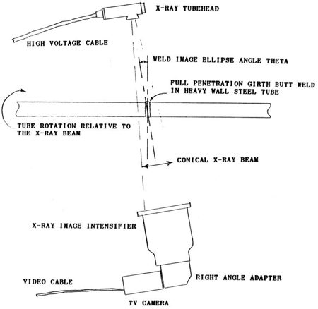
FIGURE 2: Simulated Elliptical Radioscopic Image of Full-Penetration Girth Butt Welds in Heavy Wall Steel Boiler Tube
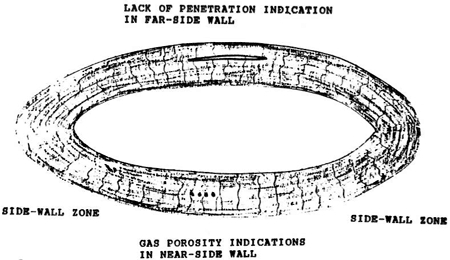
Penetrameter placement is on the X-ray tubehead side as is the accepted practice with film radiography. Double wall penetrameter image quality with image processing is on the order of 2-2T over a wide range of tube diameters and wall thicknesses. As with film radiography, sensitivity is poor in both of the side wall regions, so the weldment must be rotated through at least one complete revolution to ensure a high quality inspection.
As the weldment is rotated, the weldment is seen through a wide range of viewing angles, thereby providing increased sensitivity to laminar defects, such as cracks and lack of sidewall fusion, for heavy wall tubes, it may also be necessary to vary the weld ellipse angle to provide a good inspection of the sidewall weld prep areas.
The functional block diagram of a modern radioscopic system is shown in Figure 3. While the depicted system illustrates a girth weld inspection application, the block diagram of many other radioscopic systems would appear quite similar except for the test object and manipulator configurations. Modern radioscopic systems are highly automated, thereby reducing the operator workload. Many of the radioscopic inspection parameters can be automated. These would include X-ray parameters, such as kV, mA, digital image processor parameters and manipulator scan plans. The actual evaluation of the complex radioscopic weld image usually requires the skill of a human interpreter, although progress is being made in the automatic analysis of weld images.
FIGURE 3: Functional Block Diagram of Radioscopic System

The Challenge
From the discussions in this paper, it should be clear that there are many factors to consider in obtaining an optimized radioscopic image as compared with a radiographic image. Not only is there more to consider in terms of imaging geometry and X-ray parameters, the system configuration itself is much more variable in terms of mixing and matching components to do a specific job. On top of that, imaging system components are in a continuous state of change. Existing components are being improved and new ones added on a continuing basis. Radioscopic imaging technology turns over an average of once every five years.
Standards and codes which govern the use of radioscopy must take into account the changing and empirical nature of radioscopic system design. It is simply not possible to "cookbook" a successful radioscopic system design in the same way as a radiographic technique. Performance monitoring is another area where no one device, such as an IQI or penetrameter, will meet every need in a dynamic imaging environment.
Inspection imaging archiving is another complex area. With X-ray film the archive-quality inspection image comes as a by-product of the inspection process. With dynamic radioscopic imaging the choice of an appropriate archiving method is much more difficult. About the only practical way to capture often-important image motion is through the use of video recording with the loss of some image quality. Digital recording techniques retain 100 percent of the image quality and even permit the reevaluation of the test object without the test object being present, since the raw inspection data is captured. However, digital recording does not capture real-time motion and is very consuming of storage media at the rate of 1/4 megabyte, or more, per inspection image.
General radioscopic examination does not lend itself to be governed by a highly standardized procedure. At least two possibilities exist. One possibility is to limit the applications to which the standard applies to certain, well-specified applications where the radioscopic procedure can be highly standardized. Even in this situation the standardized procedure may have to be frequently revised as the radioscopic state-of-the art progresses.
Another possibility, and the one which ASTM (American Society for Testing Materials) has taken with E-1255, is to write a more generalized standard practice covering a wide range of radioscopic applications which require the provider and user of radioscopic services to reach agreement on certain key points. These key points include: 1) equipment qualifications, 2) test object scan plan, 3) radioscopic parameters, 4) image processing parameters, 5) image display parameters, 6) accept-reject criteria, 7) performance evaluation, 8) image archiving requirements and 9) operator qualifications.
Summary
In conclusion, radioscopic inspection is a valid and valuable NDE method which deserves to be recognized separate and apart from radiography based upon its own merits. Radiography and radioscopy cannot be compared on an apples-and-apples basis as has been the tendency in the past. Because of the dynamic nature of radioscopy, it excels at finding defects, such as cracks and laminar defects, whose detectability is highly orientation dependent. Because radioscopy produces inspection results in real-time, the possibility exists to use radioscopy as an on-line inspection technique with important process control connotations. Radioscopy can have an important role in improving the quality while at the same time reducing the manufacturing cost for a wide range of products.
Before radioscopy can find widespread acceptance as a bona fide NDE methodology, codes and standards-writing bodies must acknowledge its existence and formalize its use with appropriate codes and standards. ASTM has taken a leadership role with the issuance of E 1255-88, "Standard Practice for Radioscopic Real-Time Examination." It is hoped that other radioscopic codes and standards will soon follow [Please see ASME code Section V, Article 3 for radioscopic code and standards].
About the Author
Richard S. Peugeot is President of Peugeot Technologies, Inc., which specializes in the application of real-time radioscopic examination. He is a member of ASTM and ASNT and currently serves on the ASTM E7 committee. Mr. Peugeot was instrumental in developing ASTM E 1255-88 "Standard Practice for Radioscopic Real-Time Examination."
Editor's note: Some ASME Boiler and Pressure Vessel Code requirements may have changed because of advances in material technology and/or actual experience. The reader is cautioned to refer to the latest edition of the ASME Boiler and Pressure Vessel Code for current requirements.