Failure Avoidance in Welded Fabrication
Alan W. Pense
Professor, Associate Dean, College of Engineering and Applied Science
Lehigh University, Bethlehem, PA
Category: Design/Fabrication
Summary: The following article is a part of the National Board Technical Series. This article was originally published in the October 1988 National Board BULLETIN. (9 printed pages)
Failure avoidance is the responsibility of designers, materials engineers, fabricators, inspectors, and owners all working together.
Abstract
In spite of well developed code and other failure avoidance procedures, failures of pressure vessels and other welded components sometimes occur. Experience with failure analysis shows that many problems could be avoided by better communication between engineers of different disciplines early in the production process. With a vessel failed in hydrostatic testing as an example, the interaction between engineers that might have prevented the failure are explored and the benefits of improved interaction stressed.
Introduction
In most welded structures, a variety of controls are in existence that provide a high level of failure avoidance. For example, codes for design and fabrication of structures, inspection and inspector qualification requirements, materials specifications, and owner operational instructions all contribute in a significant way to the control of failure. Behind these codes and requirements are the combined experience of all of the engineering groups involved in their creation and periodic revision, without which they could not exist. Thus, failure avoidance has been an ongoing activity in the engineering community for a long time.
However, welded structures do fail on occasion, and pressure vessels are no exception to this fact. When this happens, there may be serious consequences, almost always in terms of financial loss, and sometimes in terms of loss of human life. Welded structures have special characteristics, some of which tend to make them more susceptible to propagating, and thus more catastrophic fractures.
For example, they are more monolithic, and discontinuities from one part of the structure can propagate by a number of mechanisms into other parts of the structure without encountering interrupting open interfaces. Another characteristic of many welded structures is residual stresses, and the effects are difficult to assess. In pressure vessels, their effects may be diminished, but not eliminated, by postweld heat treatment. Yet another consideration is the fact that welded structures contain joints that are metallurgical composite and their behavior is complex for this reason.
An important result of all of these factors, and one especially so for failure avoidance, is that there are many interactions between parts of the structure considered more critical and those considered less so in an engineering sense. While this is true to some degree of all welded structures, it is especially true of pressure vessels. There are, in fact, virtually no inconsequential parts of a pressure vessel from the failure avoidance viewpoint.
Experience with failure analysis also demonstrates 1,2,3 that some of the problems leading to failure are common to many failed structures, and thus, with some knowledge and foresight, should be avoidable. Moreover, although the author's background is with weld related problems, these failures have not necessarily been due to the execution of the welds, but many different causes.
Using as an illustration the failure of a pressure vessel, which occurred during hydrostatic testing, this paper is intended to reinforce the fact that failure avoidance is a chain of interrelated responsibilities. It is not the job of one link in the chain, but all the links working together. As failures go, this was a "good" one, occurring during the last of the many checks and balances in the system. There were no injuries. It is an instance in which, in spite of some lapses, the failure avoidance system ultimately worked. However, it can also serve as a warning that omissions and communication failures can occur, even when engineers think they are doing a good job, and the results can have serious consequences.
Engineers Working Together
Good welded fabrication is ultimately a team effort involving the designer, the materials engineer, the fabricator, the inspector and the owner. These individuals may not work for the same company, and thus may not feel the corporate responsibility that they should. In fact, the current legal system may discourage this. But even if they are employed by one company, this is no assurance that good team action will result. A fabrication engineer working for a large company once told me that sometimes he felt that the design drawings for welded fabrication were "thrown over the wall in the dark of night" from the company design group. While this may be an exaggeration, it was clear that he felt their input was not solicited as it should have been.
Indeed, if various engineers don't work together, the result is often less than, not more than, the sum of the whole. It is the author's experience that designers sometimes design structures which cannot easily be built using materials that are incompletely specified. To compound the problem, the fabricator attempts from these designs to build these structures but in such a way that they cannot really be inspected. Finally, "inspection" completed, they are turned over to an owner who then operates them in ways that the designer did not anticipate, the materials cannot tolerate, and for which the fabrication or inspection was not appropriate. This will not result in failure avoidance.
Many engineers think of the design, materials selection, fabrication and inspection of a product, such as a pressure vessel, as occurring according to a chain such as that shown in Figure 1. This approach separates engineering functions neatly but is not the optimum for failure avoidance. The appropriate model is closer to that shown in Figure 2. This model has all engineers working together in an interactive systems approach to the product. It may be an idealization that cannot be fully realized, but it will inherently result in superior failure avoidance because it results in more informed design, more rational materials selection, more efficient fabrication, and more effective inspection.
FIGURE 1: Common Conception of Product Development
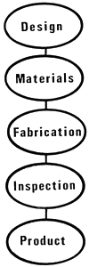
FIGURE 2: Interactive Model for Product Development
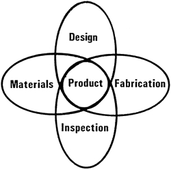
Not only will this result in greater safety but should result in lower overall cost. For example, inefficient design must somehow be compensated with stronger or tougher materials, or lower overall stresses and therefore larger parts requiring more welding and inspection. Similarly, ineffectiveness in each of the other engineering disciplines must be compensated by the rest. Thus good failure avoidance procedures are nothing more than good engineering procedures and have many benefits.
The key component left out of Figure 2 is the owner, who must somehow be aware of these interactions, if not contribute to them, so that the operation of the product will be in accord with his and the designer's engineering expectations.
Design
The best approach to failure avoidance is good design to start with, including both design of the structure and of the welded joints. While many aspects of design will be governed by code requirements or company practice, the designer still exerts a significant influence on stress concentrations, particularly those close to and around welds. This is especially important in high cycle live loaded structures where the stress concentrations at weld toes, in association with defects inherent to those locations, may control structural performance. It is also important in pressure vessels from the brittle fracture viewpoint, and because creep and low cycle fatigue requirements are often involved. While the overall stress raising effects of typical welds are well known, design incorporating welds of inappropriate type or at inappropriate locations still occur.
Again, there are also occasional examples of welded details that are poorly designed from the fabrication viewpoint and that subsequently fail because they were difficult or even impossible to execute. A critical examination of these details by the fabricator, or the designer in consultation with the fabricator, would have revealed that they could not be executed as intended. Thus, a problem could have been predicted in advance and avoided. Most failures in structures originate at connections, and this is in spite of the fact that more time and effort is spent on their design, materials, fabrication, and inspection than most other parts of the structure. More time in this area is still time well spent, however.
Materials Selection
Materials selection may be considered a special subdivision of design because materials are often specified by designers and sometimes owners. However, it is a field that requires specialized training and thus is usually considered an independent engineering function. Regardless of who prepares the materials specification, one of the most common problems is failure to account for all the properties needed. For example, strength properties (which usually incidentally includes tensile ductility) are normally specified. On the other hand, toughness properties are seldom specified. Fabrication related properties, such as weldability or ductility for mechanical forming, are almost never specified.
In general, engineers have relied on materials to be "forgiving" in terms of ductility, toughness or weldability. That is, they have relied on their experience with respect to these unspecified but important properties for the materials they are accustomed to using rather than specifying them (which will undoubtedly increase their cost). For example, they may rely on indirect provisions in ASTM (American Society for Testing Materials) steel specifications, such as a steel being made to fine grain practice, as an indication of toughness. But unspecified properties critical to a given application are probably unknown to the materials supplier, and may not be provided, with a failure being the result. It is the author's experience that this is one of the more common causes of failures. The materials specifier must develop an awareness of all the properties required for a given application and identify them accordingly.
Fabrication
Good fabrication generally means attention to detail, and it, too, is essential for failure avoidance. As a minimum, this requires understanding of and adherence to the relevant codes. They represent the corporate experience of many segments of the industry and should not be taken lightly. Code requirements for welding documentation and control such as preheat, postheat, care of consumables, and operator skill levels need to be observed. The author has sometimes found codes and specifications treated as if they were desirable goals and not minimum performance standards. From the failure avoidance viewpoint, they are the starting point, not the end point, of control.
Effective fabrication also requires knowledge beyond what is in the relevant codes. There are scores of fabrication procedures, techniques, and practices which are not incorporated in codes but which are essential to effective fabrication. These must also be part of the fabricator's operating experience if failures are to be avoided. More than one failure can be traced to the use by a fabricator of a material or technique with which he was not really familiar and for which he did not get the needed background.
One of the special problems in fabrication is repair welding or, in an extreme case, retrofitting, of a finished product. Repair welding of a structure, such as a pressure vessel, is usually more difficult than initial welding, and requires more, rather than less, care. The vessel is more highly constrained, is more difficult to access, is harder to preheat and postheat than before, and sometimes is also harder to inspect. All this puts a premium on doing things right the first time and on special control of quality when repairs are to be done. The most difficult of repairs are field modifications. These have all of the problems indicated above and also the problem of the control of welding and inspection in the field.
Inspection
Fabrication is seldom perfect, and thus good inspection is also required for failure avoidance. Welds need to be planned so that they can be inspected, and then an inspection procedure established which accomplishes this to an adequate degree. Quality cannot be inspected in the attempt to make an inferior product a superior one by upgrading it through inspection. It is a risk at best and an expensive one as well. Appropriate inspection can verify the quality of a product and catch the occasional discontinuities that may occur. The current trend in codes is toward inspection requirements which are appropriate for service. This is a reasonable approach, and then there need not be any compromises on the quality expected or required.
Operation
The final step in failure avoidance is control of operation. No amount of careful design, good fabrication, and expert inspection will compensate for the failure to establish and control operating limits on equipment. Designs are usually conservative, but there are boundaries over which operations cannot go without major consequences. Overstressed pressure vessels will fracture, overloaded bolts fail and unprotected metals corrode. Operating equipment needs to be maintained and periodically inspected. Operators of equipment share with designers, fabricators and inspectors the responsibility for failure avoidance.
One recurring problem related to operation is owner modification which makes a structure such as a pressure containing component more failure prone. A number of causes may be identified. The first is modification which increases capacity in such a way that parts of the vessel are now overstressed. A second is modification which introduces stress concentrations through carelessly considered design changes. A third is poor quality workmanship which introduces discontinuities in the structure. Failure avoidance means that the same rules for repair mentioned above be applied for owner modifications.
Case Study: Vessel Failure In Hydrostatic Testing
Most of the above components are brought together in the case study described here. It occurred some years ago and some details are omitted. It is, however, not unique, as anyone who has worked on the analysis of failed pressure vessels and other structures can testify. There may be a tendency to think that the problems described "can't happen here." It is the author's opinion that they happen more often than engineers would like to think but do not come together in such a way as to cause failure. In this our system serves us well but should not be relied on to save us in all instances.
Design and Materials Selection
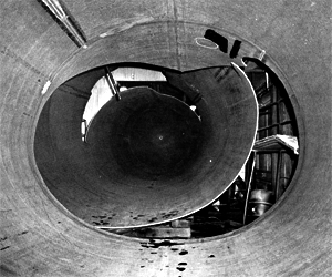
The failed pressure vessel is shown in Figures 3 and 4. As can be seen, the pressure vessel failed by a fast fracture that not only ran down a good portion of the length of the vessel (Figure 3) but also severed it in half (Figure 4). The vessel was made of 20.6 mm (.81 in) thick C-Mn steel and was to be used for static liquefied gas storage. The length was about 28 m (92 ft) long and the diameter about 3.3 m (11 ft). It was designed according to Section VIII, Division I, of the (American Society of Mechanical Engineers)ASME Boiler and Pressure Vessel Code and had a capacity of 254 m3 (60,000 gal). The maximum design stress in the membrane was 140 MPa (20.25 ksi) which was to be one quarter of the steel tensile strength. The vessel had the two small set-on nozzles fillet welded into the shell seen in Figure 3.
FIGURE 3: Failed Pressure Vessel after Hydrotesting
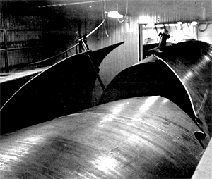
FIGURE 4: Fracture Pattern in Failed Vessel
The shell courses were submerged arc welded with the nozzles being manually welded. Low hydrogen consumables were used. The main seam welds were inspected by radiography, but the nozzle welds were inspected by surface techniques. No preheat was used unless the ambient temperature was below 10oC (50oF), and then a preheat of 27oC (80o F) was applied. No postweld heat treatment was used.
The material used had a yield strength requirement of 345 MPa (50 ksi) and a tensile strength requirement of 558-696 MPa (81-101 ksi). This was somewhat higher in strength than the fabricator was historically used to, but had adopted the steel for this application because it permitted fabrication of thinner, more economical vessels. There was no toughness specification for the material. Postweld heat treatment had been used in the past for vessels of this type but, in the current application, purchasers did not require it, so it was discontinued for economic reasons. A number of these vessels had been built in recent years without any problems prior to this failure. On the surface there was nothing to distinguish this vessel from the others.
Material Variability
A close examination of the events surrounding the failure revealed that this vessel was different from the others in several important respects. For example, the material was within but toward the top of the permissible composition limits for the specification. Both carbon and manganese contents were relatively high. In addition, molybdenum was present at 0.05%, the maximum level permitted, and there had been an addition of 0.05% vanadium which was neither specified nor prohibited for this grade. Discussions with the steel supplier revealed that there was some concern in the mill about producing material at the strength level required, and thus composition adjustments were being made to insure that the minimum tensile strength would be met in this type of plate. There was an indication that some material had to be rejected for this reason, and there was naturally an effort to avoid this in the future.
It turned out that one cause for concern on the part of the mill was the requirement that all tension test coupons be stress relieved prior to testing to simulate a postweld heat treatment. This had the potential for reducing their strength below the minimum, and there was an effort to compensate for this. For the material in these vessels there was no need for this requirement. However, the purchasing department had added this to the order because it had been their custom to do so even though it was not requested.
Tests by the supplier showed that, in fact, the steel from the failure initiation site and other parts of the vessel had an as-rolled tensile strength of 740 MPa (107.5 ksi). well over the specified limit, but the stress relief treatment, at 620oC (1150o F), reduced it to 680 MPa (98.7 ksi) which was within the specification. The vessel itself was not postweld heat treated, and thus the material was at its as-rolled strength. The material was about 100MPa (14.5 ksi) higher in tensile strength than most other heats of this steel.
The higher strength of the steel had significant implications with respect to toughness and weldability. The 20J (15 ft-lb) transition temperature for the steel was around 20oC (68oF) while most previous heats had a transition temperature closer to -10oC (16oF), although an occasional heat had a transition temperature of 5oC (40o F). The high level of strength and the level of carbon and alloys, although within specification, resulted in reduced weldability.
Fabrication Factors
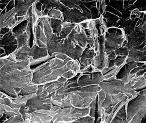
The material variations discussed above had an effect on subsequent events. Examination of the fracture surfaces of the failed vessel, seen in Figures 5 and 6, indicated that the microscopic failure mechanism was brittle cleavage or quasi-cleavage, demonstrating that fracture occurred below the transition temperature for the material. The initiation site was established as being at the edge of a manual fillet weld that was around a nozzle like the one seen in Figure 5. The weld was made in an unheated shop in which the temperature was above the minimum for preheat but probably below 15oC (59o F). The source of fracture was found to be a hydrogen induced code or delayed crack at the toe of a repair weld.
FIGURE 5: Macroscopic Fracture Surface Appearance
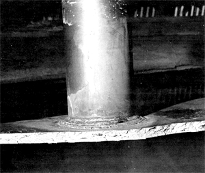
FIGURE 6: Scanning Electron Micrograph Showing
Typical Appearance of Fracture Surface, 1500X
During or after fabrication, a visual inspection of the joint had shown some surface discontinuities and these were repaired by placing additional short passes, generally not more than 25mm (1 in) long, on the existing weld. The extent of subsequent inspection is unknown. The hardness of the heat affected zone in this location was over RC40, high enough to indicate martensite, a condition which in combination with excessive hydrogen in the arc atmosphere during welding provides both the potential for and presence of hydrogen induced (cold) cracking.4 Figures 7 and 8 show the heat affected zone microstructure and the fracture surface appearance in the initiation area.
FIGURE 7: Weld and Heat Affected Zone Microstructure at the Toe of the Repair Weld.
Note Hardness Indentation. Nital Etch, 50X
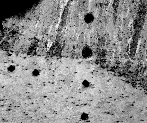
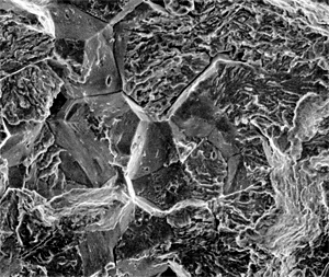
FIGURE 8: Scanning Electron Micrograph of the Fracture Initiation Zone
Showing Intergranular and Quasicleavage Fracture Areas, 2000X
Using a fracture mechanics model and the Charpy V-notch toughness data for the steel, it was possible to show that the size of the defect, in conjunction with the residual and applied hydrostatic test stresses, was sufficient to cause fracture of the vessel.
It is probable that the limited toughness and weldability of the steel in combination with excessive hydrogen in the welding arc made the normally effective welding procedures inadequate to prevent cracking, at least for the nozzle welds. However, it is also the author's opinion that the welding of this part of the vessel was considered less important than that of the main seams and did not get as much attention. The use of short repair passes on weldments is not good practice as the arc energy is quickly dissipated in the base metal and results in very high cooling rates in heat affected zone, promoting martensite formation and cracking when excessive hydrogen is present in the welding arc.
Inspection Considerations
Initially it should be noted that, while inspection of the vessel was in accord with typical practice, the inspection of the nozzles was at a different level than the main seams of the vessel. This was, in part, because the design of the nozzle would not permit meaningful inspection by other than surface techniques. Failure to obtain a good inspection of the nozzle welds was, without a doubt, a contributor to the failure.
A second contributor was the conditions of the hydrostatic test itself. The water used for the test was taken from a sump and was at a temperature of less than 15oC (59oF), and perhaps less than 10oC (50o F), which was the ground water temperature at that time of year. After reaching the test pressure, the vessel was left under pressure for a period of hours. It reportedly failed during the night when no one was present.
It was also reported that the vessel was pressurized to 2.79 MPa (400 psi) although the vessel specification only required a test pressure of 2.58 MPa (375 psi). This represents an overpressure of 10% or a test at 1.6 times the working pressure of the vessel. While this may not have contributed materially to the failure, it may have produced additional plastic strain in the vicinity of the nozzles where the fracture ultimately started.
Corrective Measures
In the aftermath of the vessel failure, all of the above information came to light. As a result, a series of preventive measures were undertaken. Some immediate action was required as a number of additional vessels made of the same heat of steel were in various stages of fabrication. The following steps were taken at once. (1) All nozzle welds were carefully inspected and all repairs made with a preheat of 121oC (250oF). Very short repair welds were prohibited. (2) Currently fabricated vessels were postweld heat treated at 620oC (1150o F) prior to hydrostatic testing. (3) Nozzle cutouts were to be used to sample material toughness, with the option being to heat the water for testing if the transition temperature of specific vessels was high.
The long term solutions incorporated some of the above measures but centered on better assessment of material properties, especially strength and toughness, actually needed in future vessels. The fabricator and steel supplier both participated. These measures did not necessarily include a toughness specification for the steel or continued postweld heat treatment of the vessels.
Summary
The case study cited above is intended to provide a practical focus for the points made before. While every detail is not reported, nor every potential problem illustrated, there are enough to demonstrate that potential gaps in the engineering process can exist. Perhaps bringing together the relevant engineers for a thorough discussion of the pros and cons of design stress levels, the materials available and their properties, the implications materials and design for fabrication and inspection, might have prevented this failure. Identifying the role of toughness, in the fabrication and testing, if not the operation of the vessel, would have been helpful in preventing the failure.
Since the vessel eventually had to be, for the most part, scrapped, it is probable that the cost of such additional consultation would have been less than the replacement cost of the vessel. It would certainly have eliminated the cost and delay of the failure analysis and the outside "experts" consultants. It might even have identified a more economical design, a better material, a more efficient fabrication procedure and a more effective testing sequence, and thus a better and more economical vessel. One thing failures do accomplish is to get a lot of engineers' attentions and get them working together. A better approach might be to do so without the impetus of an engineering failure.
References
- Fisher, J.W., Pense A. W., and Robert, R. R., "The Failure of the Lafayette Street Bridge -- Influence of Designs," Prevention of Structural Failures, Materials/Metalworking Technology Series, American Society of Metals, 1978, pp 3-28.
- Roberts. R. R., and Pense A. W., "Basics of Failure Analysis of Large Structures," Civil Engineering, Vol. 52, No. 5 (May 1980), pp 64-67 (Part I) No. 7 (July 1980), pp 60-62 (Part II).
- Pense, A. W., Dias, R., and Fisher, J. W., "Examination and Repair of Bridge Structures," The Welding Journal, Vol. 63, No.4 (April 1984), pp 19-25.
- Interrante,C. G., Dalder, E. N. C. and Yeo, R. B. G., "Effect of Moisture on Cold Cracking of a Carbon-Manganese Steel," The Welding Journal, Vol. 48, No. 9 (September 1969).
Editor's note: Some ASME Boiler and Pressure Vessel Code requirements may have changed because of advances in material technology and/or actual experience. The reader is cautioned to refer to the latest edition of the ASME Boiler and Pressure Vessel Code for current requirements.