Finite Element Analysis of Pressure Vessels
J.W. Jones
President of Swanson Service Corporation
58th General Meeting in 1989
Category: Design/Fabrication
Summary: The following article is a part of National Board Classic Series and it was published in the National Board BULLETIN. (7 printed pages)
The following material represents the author only and should not be assumed to be the opinion or policy of The National Board of Boiler and Pressure Vessel Inspectors or the American Society of Mechanical Engineers administration, staff or membership, unless so acknowledged.
The use of finite element methods to design and analyze pressure vessels is a relatively recent development in the overall historical perspective of the ASME Code. The finite element method first became a useful tool for the designer in the early 1960s. The advent of the ASME Nuclear Code, Section III, which first appeared in about 1964, provided for a "design by analysis" procedure. Up until this time, the pressure vessel design codes all used the "design by formula" approach, which is essentially that now used in Section VIII, Division 1 of the ASME Code. The design by formula method provides explicit rules for calculating wall thicknesses of heads, shells, reinforcement around openings, and other details of a vessel. There are additional rules to handle such features as discontinuities between different components (i.e., the 3:1 taper rule) and allowable construction details are illustrated. The shortcoming of these rules is, of course, that they cannot cover every conceivable detail that the designer may want to use. For example, Section VIII, Division 1 gives numerous warnings and admonitions that the designer shall consider the effects of thermal gradients, piping loads, nozzle loads, rapidly fluctuating loads, seismic, wind, etc., but unfortunately there are few specific guidelines or formulas included in the code to cover such items. Further, the allowable stresses given in the code are based on a rather simplistic average membrane stress. Other loads, such as thermal loads, for example, cause a different type of stress that cannot be limited to the S values in the code, if a reasonable design is to be developed.
Section III and Section VIII, Division 2, which came out several years after Section III, both use the concept of design by analysis. These rules provide the designer/analyst with a variety of stress limits, each developed to protect against a different mode of failure. Stresses are classified into categories such as Primary, Secondary, Peak, etc. Each category of stress is subjected to different stress limits. Essentially, the Nuclear Code and Division 2 of Section VIII require that the designer/analyst be able to calculate the stresses everywhere in the vessel, not just the average membrane stresses in regular sections (such as cylinders and dished heads).
Early evaluation of nuclear vessels was performed using discontinuity analyses. This technique requires that the vessel be approximated by a series of simpler shapes, such as cylinders, cones, rings, etc. The stresses are found by matching the displacement and rotations of each section (compatibility) while satisfying equilibrium of the loads. The method is very useful and forms the basis for the present flange design rules in the current codes. The problem is, however, the time-consuming nature of the technique for the engineer who must set up and solve the equations, and the necessity to approximate complex shapes with simpler geometries, for which analytical (i.e., closed form) solutions are available. Furthermore, it is difficult to include thermal stress effects in a discontinuity analysis.
The first commercially useful finite element program was developed about the early to mid-1960s. This early program was actually little more than an automated discontinuity analysis. Conical shell elements were employed to model axisymmetric shapes. Each element was essentially a short conical shell or ring. The loads were applied to each element and equilibrium and compatibility relationships were used to provide for a solution. Carl Friedrich1 , whom the author had the privilege of knowing at Westinghouse Bettis Atomic Power Laboratory, developed an excellent program for two-dimensional axisymmetric structures. This program was used extensively for the analysis of naval nuclear pressure vessels well up into the 1970s.
The first true finite element programs were introduced about this time. Wilson2 and Clough and Rashid3 at the University of California, Berkeley were some of the pioneers of this technology. The first program that the author personally applied was known as FEATS, which was a product of the Berkeley work. These programs utilized constant strain quadrilateral and triangular elements. The analyses were restricted to either plane stress, plane strain or, the most useful for the vessel designer, axisymmetric geometries. This provided the designer/analyst with a very useful tool for modeling complex structures.
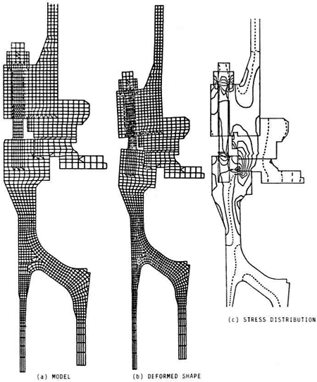
As an example of the usefulness of these programs, consider the naval nuclear plant main coolant pump shown in Figure 1. This pump has been undergoing a series of operational tests which involved both pressure and thermal transient cycling. After several months of testing, the pump was shut down and disassembled to evaluate wear and other operational effects. The flange on the pump casing was found to have rotated and permanently deformed, capturing the thermal barrier, and thus preventing the removal of the motor from the pump body. After much effort and extensive use of the overhead crane, the pump was eventually disassembled. However, the disassembly procedure was not likely to be acceptable to the Navy, and an intensive analysis effort was begun to determine the cause of the failure and, perhaps more importantly, to determine if the existing pump casings could be used for production pumps. A two-dimensional finite element model for the FEATS program was developed. While the analysis may seem relatively crude today, we felt at the time that it represented the state-of-the-art in analysis techniques. The FEATS program permitted orthotropic material properties, so the flanges and flange bolts were modeled in such a way that the flexibility of the components in all directions was preserved. This required, for example, that the hoop or circumferential stiffness of the bolts be reduced to essentially zero while preserving the axial and bending stiffness. Note in Figure 2 that the bolt elements were overlaid so that the bolts could move independently of the flange. The bolt was also represented by a ring of elements, so it was necessary to modify the bolt width to preserve the correct stiffness. The thermal analysis was performed using a finite difference program. The resulting temperatures were input to the finite element model through a special purpose FORTRAN program that was written for this project to interpolate the thermal results and calculate finite element nodal temperatures. The deformed geometry plots and the stress distribution due to bolt preload are shown in Figures 2(b) and 2(c) . The rotation of the flange can clearly be seen.
FIGURE 1: Main Coolant Pump
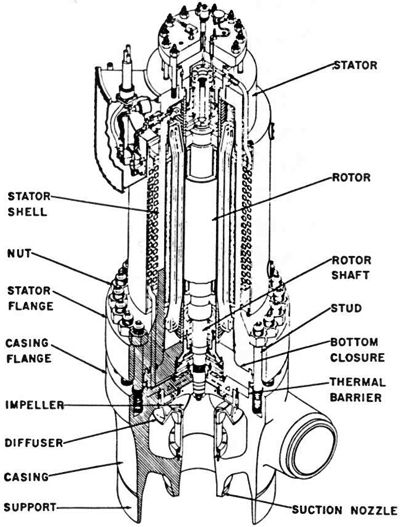
FIGURE 2: Finite Element Model of Pump
Suffice it to say that this project represented a tremendous amount of manpower. There were four or five of us working on the project for approximately six months. A similar project could be done today by one experienced person in approximately one month. The computer that was used to run the analysis was an extremely expensive mainframe (usually reserved for nuclear physics calculations). Now the entire job could easily be done on a personal computer. Maybe the most telling comparison is that it would probably cost less than one-fourth as much to do the total job today - and in 1968 a dollar was worth a lot more.
Two-dimensional finite element analysis is impressive, but the world is three-dimensional. Consider the aforementioned pump geometry. Only by ignoring the exit nozzle altogether can the problem be considered two-dimensional. The first attempts to represent three-dimensional effects (other than axisymmetric considerations) were to include nonsymmetric loading as an axisymmetric geometry. Kalnins1 developed such a program in the mid-1960s that found limited application in the pressure vessel industry. The basic approach is to assume a harmonically varying displacement solution, expand the applied loading in terms of these harmonics and solve for each harmonic separately. By summing the harmonic solutions such as in a Fourier Series expansion, an approximate solution for the symmetric structure subjected to nonsymmetric loading can be developed. This technique was especially useful for certain cases like a simple overturning moment (Fourier Series mode N=1), but it was cumbersome to use for more general loadings. The approach was never widely used in the pressure vessel industry for anything but occasional nuclear component analyses.
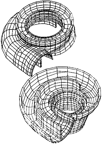
Two new elements appeared on the commercial scene about 1970 that made three-dimensional analysis feasible for the designer/analyst. These were the three-dimensional solid and shell elements. Figure 3 shows a three-dimensional solid element model of a pump casing (circa 1978). Three-dimensional pressure vessel analyses were quite scarce for a number of years, even after the technology was developed. An article5 published in 1972 in Machine Design was considered quite avant-garde and the finite element model was used on the cover of the magazine. There was a saying about that time that a person was "knowledgeable if he was aware of the technology, qualified to perform such an analysis if he had seen it done before, and was an expert if he had done one himself". The ANSYSR 6 general purpose finite element program was one of the first commercially available computer programs that had a full three-dimensional analysis capability. ANSYS also had one other attribute that was very important to the pressure vessel designer/analyst. The same finite element mesh or model could be used for the thermal analysis. Thus, it was not necessary to run a separate thermal program to calculate temperatures for use in the analysis of thermal stresses.
FIGURE 3: Finite Element Model of Pump Casing
The three-dimensional shell element allowed the vessel designer much greater flexibility in developing finite element models. Since a great majority of pressure vessels are relatively thin-walled, the shell element enables the designer/analyst to model a complex vessel complete with nozzles, supports and other nonaxisymmetric components. Whereas the three-dimensional solid element can be used for these analyses, there are efficiencies in modeling and solution that often favor the shell element. Now the basic tool kit was complete with axisymmetric shell and solid elements and three-dimensional shell and solid elements. Future developments continue to refine these basic tools.
Now, let's examine examples of some of the ways the finite element method is used today. Perhaps one of the most useful papers ever written in the field of pressure vessel analysis was on the design of supports for horizontal vessels by L. P. Zick7 . This paper has been used extensively for approximately 40 years.
Widera, et. al.8 have recently published an excellent paper on the finite element analysis of horizontal vessels. This reference also contains a review of the work from previous investigations in this area. While it is now becoming clear from these analyses that the Zick results are somewhat less than exact, it is also remarkable and a tribute to Mr. Zick that the vast number of vessels designed using the Zick method have operated safely for so long.
The Zick solution, however, is limited to consideration of the dead weight of the vessel and contents for a rather specific saddle design configuration. Figures 4 through 7 show finite element models developed by the author for a number of projects, which involved horizontal vessels. These were necessitated by the fact that the Zick method did not cover the geometry or the loading condition. Figure 6, for example, shows the deformed shape of a vessel subjected to axial seismic loads. Horizontal storage tanks are generally fixed at one saddle and the other is allowed to move to accommodate thermal expansion. Thus, all the seismic load must be taken by the fixed saddle. This can result in very high local bending stresses on the shell due to the overturning moment on the saddle. The particular analyses for which the model was developed were for an existing tank. The application of seismic loads greatly overstressed the tank as designed. In order to reduce the stresses to an acceptable level, a series of gusset plates were added to the saddle. This reduced the overturning moment on the shell and consequently the stresses were reduced (Figure 7). The use of the finite element analysis showed that the existing saddle would be adequate after bracing and increasing the foundation. No welding was required on the shell of the pressure vessel which always provides comfort to the inspector.
FIGURE 4: Stress Distribution in Horizontal Vessel
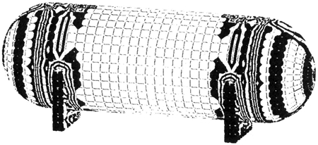
FIGURE 5: Finite Element Model and Deformed Shape Plot for Horizontal Vessel with Ring Type Support
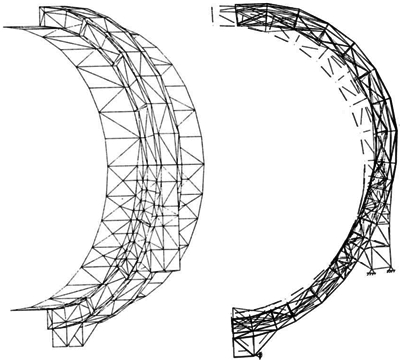
FIGURE 6: Deformed Shape Plot and Stress Distribution for Axial Siesmic Analysis of Horizontal Vessel (Stress Values in KSI)
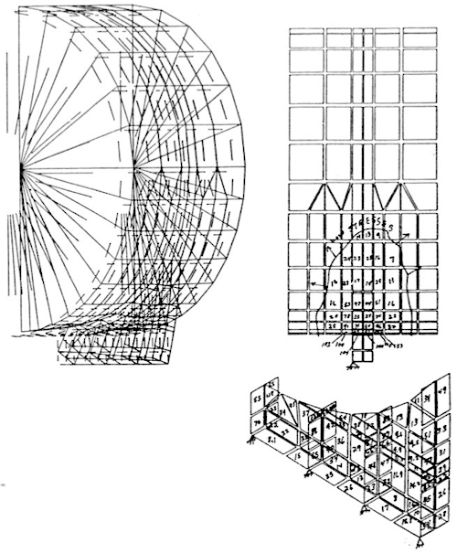
FIGURE 7: Deformed Shape Plot and Stress Distribution for Axial Seismic after Addition of Gusset Plates (Stresses in KSI)
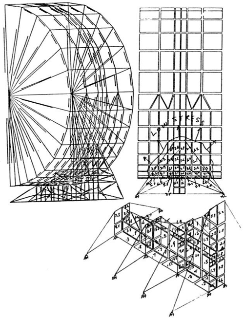
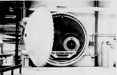
Another area where finite element analysis is becoming more widely used is the design and analysis of quick-opening closures. The quick-opening closure is almost by definition one which will be cycled many times during its lifetime. Snow9 recently gave an excellent paper in which he pointed out some of the dangers of the quick-opening closure and gave some examples of the consequences of failures that have been experienced. The use of composite materials, which require curing at temperature and pressure, is creating a need for more and more autoclaves, most of which require quick-opening closures. Quick-opening closures are also used extensively in the food processing and pharmaceutical industries. Recent experience has shown that even the hydrotest is not an adequate test for guaranteeing the safety of an autoclave. In the fall of 1988, an explosion in Orange County, California, which caused death and injury, happened during the first actual cycle of operation, even though a hydrotest had been performed prior to the operation. A quick-opening closure is generally a complex piece of machin-ery that is subjected to pressure, temperature transients and relatively high numbers of loading cycles. Additionally, the elements of the closure are generally not amenable to closed-form (design by formula) evaluation. This provides an excellent opportunity for using the finite element analysis method. Figures 8 and 9 show a finite element model used by the author to analyze a large (15-foot diameter) rotating-ring-interrupted-flange type closure. Figure 10 shows a similar design by my associate, Alfred M. Smolen.
FIGURE 8: Finite Element Models of 15-Foot Diameter Quick-Opening Closure
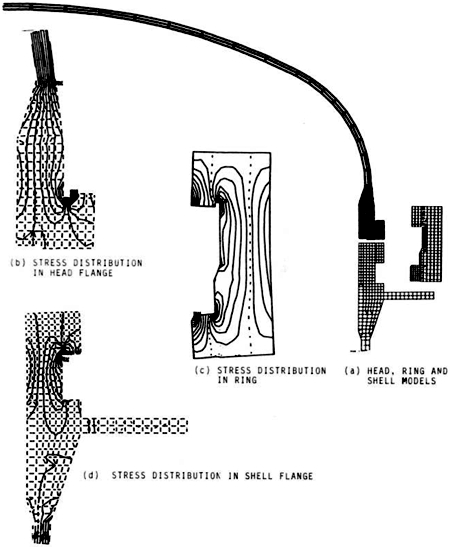
FIGURE 9: Stresses at Local Radii in Locking Ring
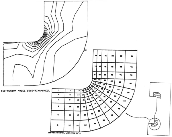
FIGURE 10: Quick-Opening Closure
While the model may appear to be two-dimensional, it is actually three-dimensional. The cyclic symmetry of the lug design allows the analyst to model only one complete set of lugs. It is evident to me, at least, that a vessel of this complexity requires a great deal more design analysis than the average Section VIII Division 1 vessel. Clearly, the formulas in the code are not intended to cover a design of this type.
The analysis model included the head, shell and closure ring as separate parts. Three-dimensional gap elements were used to model the interface between each of the components. Contact surfaces were found by iterating on the solution so that the effects of deflection and rotations due to pressure (and temperature) could be included. A relatively new technique, the "cut-boundary" displacement method, was used to determine the effect of the local fillet radii at the base of the lugs and in the closure ring (Figure 9) . With this analysis method, a detailed stress analysis was performed and the fatigue life of the closure was determined. Recommendations were also made on how to extend the service life of the vessel based upon the finite element analyses. The analysis was performed for about $15,000. This was a very small percentage of the total cost of the vessel and its installation.
It is my opinion that all new designs for quick-actuating closures should be designed and analyzed using the finite element analysis method. It should be a requirement that the owner prepare a design specification for the vessel which would give the expected operating history of the vessel. This should be signed by a registered professional engineer who is knowledgeable in this discipline. The design should be evaluated in accordance with the requirements of Section VIII, Division 2, and the results included in a design report, signed by a registered professional engineer. I believe that we should go one step further, by requiring some type of follow-up inspection. The operating history of the vessel should be recorded and compared to the Owners Design Specification. When the vessel reaches the end of its design life, it should be taken out of service or repaired to eliminate components which exceed the fatigue life predicted by the analysis.
Why not just require that the vessel be built to Section VIII, Division 2? Of course, that would be one alternative; however, a large number of Division 1 shops are adequate to fabricate these closures. The burden for additional requirements, as I see it, is on the designer and the user, not the shop. It is recognized that there are many companies that are building quick-opening closures that have operated safely for years. Clearly, such a safety record for existing designs should exempt them from these requirements. However, with the trend toward higher operating pressures and temperatures, and with the desire to increase production rates, the above requirements would seem to be necessary and prudent.
The burden of such analyses is not onerous. The use of finite element techniques is no longer limited to large companies and research laboratories. There are a large number of engineers who have experience in the analysis of pressure vessels, using commercially available computer programs and relatively inexpensive computers. Requiring that a detailed evaluation be performed as suggested should not present an undue finan-cial burden to anyone in this business.
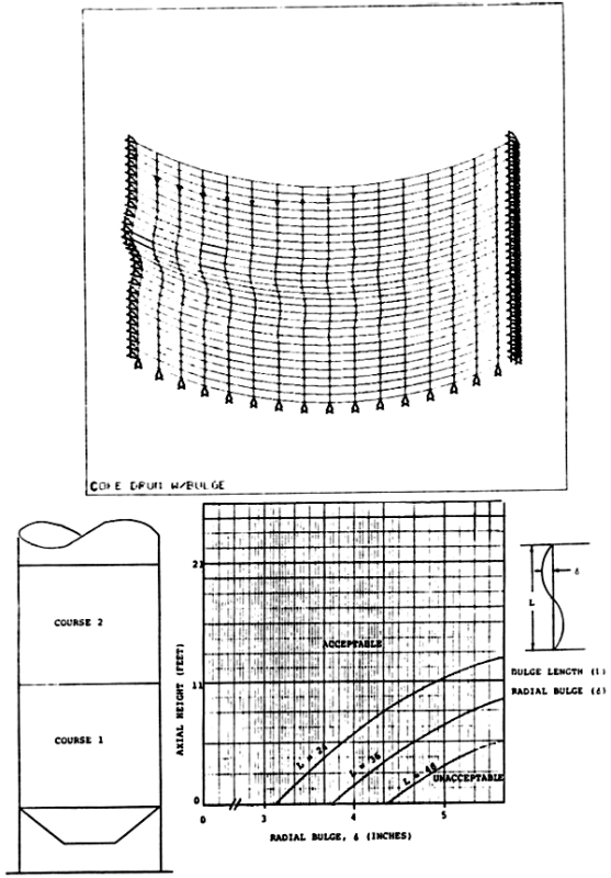
As a final example, consider stability or buckling calculations for coke drums used in the petroleum refining industry. These vessels are subjected to repeated thermal cycling at approximately 18-hour intervals. These vessels almost invariably develop bulges or indentations out-of-plane, presumably as a result of high thermal stresses induced by the process. It was desired to determine how much deformation was acceptable before the vessel should be taken out of service or repaired. This required a quite complex finite element analysis in which a parametric study was performed for a wide range of defect geometries and out-of-plane deformation magni-tudes. The solution required a large-displacement nonlinear analysis. Figure 11 shows a typical finite element model used on this analysis. Reference (10) contains a much more detailed description of the problem. The real importance of this example is not, however, the details of how the solution was obtained, but using the finite element method a simple graph could be developed for use by the inspection department. The results of these analyses were reduced to one figure that was easily interpreted by the inspector during shut-down to determine if a defect was acceptable for continued service of the vessel.
FIGURE 11: Finite Element Model to Determine Coke Drum Buckling Loads and the Resulting Design Curves
The use of finite element analysis in the design of pressure vessels has come a long way in the last 20 to 25 years. Once the domain of the specialist in a few locations around the country, the technique is available and widely used by a large number of engineers in all industries. The cost of doing such analyses has steadily declined. Hardware costs continue to decrease and the software has improved to the point that the engineering time necessary to perform such analyses has also dropped faster than salaries have risen. These trends will continue. New modeling techniques are being developed to automate the finite element meshing. The use of graphics to check the model and display results continues to improve. Many Computer Aided Design (CAD) systems have finite element meshing capability so that, once the design is entered into the CAD system, the engineer can develop a finite element model very quickly without re-entering the geometry. I believe the time has come to require that this technology be applied to certain vessels which traditionally are designed by formula. A good place to start is with vessels which utilize the quick-opening closure.
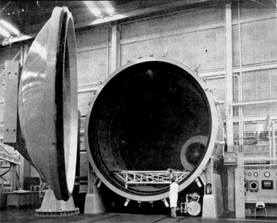
In closing, I would like to leave you with the following food for thought. Figure 12 shows a very large quick-opening closure that was designed by Alfred Smolen some years ago. This vessel is in daily operation at the Tulsa airport, through which many of us passed to come to this meeting. This vessel points directly at the runway near the terminal.
FIGURE 12: Quick-Opening Closure at Tulsa Airport 22 Feet in Diameter
Acknowledgements
I would like to thank Alfred M. Smolen for his invaluable comments and suggestions, especially in the area of quick-opening closures. I also would like to acknowledge the contribution of R.E. Nickell who generously reviewed the draft of this paper and made many valuable comments. Dr. Nickell, who was one of the early developers of the finite element methodology while at the University of California, Berkeley, was very helpful in providing additional background information that added significantly to the content.
References
1. Friedrich, C.M., "Seal Shell-2, A Computer Program for the Stress Analysis of a Thick Shell of Revolution with Axisymmetric Pres-sure, Temperatures and Distributed Loads", WAPD-TM-398, Westinghouse Bettis Aton-tic Power Laboratory, Pittsburgh, PA 1963.
2.Ed Wilson, E.L., "Finite Element Analysis of Two-Dimensional Structures," "Structural Engineering Laboratory Report No. 63-2", University of California, Berkeley, CA, June, 1963.
3.R.W. Clough and Y. Rashid, "Finite Element Analysis of Axisymmetric Solids",Journal of the EngineeringMechanics Division, A.S.C.E.Volumes 91, No. EM1, Proc. Paper 4429, February 1965, pp. 71-85.
4. Kalnins, A., "Analysis of Shells of Revolution Subjected to Symmetrical and Nonsymmetrical Loads", J. Appl. Mech. 31, 467-476 (1964).
5.Jones, J.W. - 3-D Stress Analysis, Machine Design, August 10, 1972, pp. 84-89.
6.Swanson, John A., DeSalvo, G. ANSYS Users Manual, Swanson Analysis Systems, Inc., P.O. Box 65, Houston, PA 15342.
7.Zick, L.P., "Stress in Large Horizontal Pressure Vessels on Two Saddle Supports", The Welding Journal Research Supplement, 1951, pp. 435-445.
8.Widera, G.E.O., Sang, Z.F., Natarajan, R., "On The Design Of Horizontal Pressure Vessels", Journal of Pressure Vessel Technology, November 1988, Volume 11 0/pp. 393-401.
9.Snow, M.L., "Quick Actuating Closures", The National Board BULLETIN April 1986, The National Board of Boiler and PressureVessel Inspectors.
10.DiRienz, K.A., and Jones, J.W., Analysis of Petro-Chen-tical Equip-ment Using The ANSYS Program to be presented at the 1989 ANSYS Conference and Exhibition, Pittsburgh, PA.
Editor's note: Some ASME Boiler and Pressure Vessel Code requirements may have changed because of advances in material technology and/or actual experience. The reader is cautioned to refer to the latest edition of the ASME Boiler and Pressure Vessel Code for current requirements.