Quick-Actuating Door Failures
Alexis Flippen and D.A. Zimmer
Alexis Flippen is a senior system safety engineer for Boeing Aerospace
Operations at NASA Ames Research Center
59th General Meeting in 1989
Category: Design/Fabrication
Summary: The following article is a part of National Board Classic Series and it was published in the National Board BULLETIN.
The following material represents the author only and should not be assumed to be the opinion of The National Board of Boiler and Pressure Vessel Inspectors or the American Society of Mechanical Engineers administration, staff, or membership, unless so acknowledged.
Abstract
Safety is of the utmost importance at NASA. At the Ames Research Center, a quick-actuating door has been incorporated into the redesigned test section of a pressurized wind tunnel undergoing restoration. Because typical damage from a quick-actuating pressure vessel door failure can be catastrophic, a study was undertaken to ensure that all known failure modes would be accounted for in the final design, construction, and maintenance of such a wind tunnel door. Longitudinal failure data associated with comparable quick-actuating pressure vessel doors were collected and analyzed from a wide variety of industry and technical sources and data bases, and provided to NASA engineers to assess the overall safety of the door design. In this paper, the method of analysis is reviewed, typical pitfalls in data reduction are identified, and important lessons learned and resultant recommendations are highlighted so that these can be of benefit to other design organizations faced with similar critical decisions. Finally, a brief discussion about the benefits of effective government-industry cooperation is included.
Introduction & Background
Typical damage from the failure of a quick-actuating pressure vessel door can be catastrophic, resulting in death or disabling injury and loss or extensive damage to buildings and equipment. Based on potential damage estimates, one major insurer in 1989 alone obtained premiums in excess of $167 million for pressure vessel (autoclave) policy coverage.1
In the era following the tragic Challenger accident, safety has been given even greater emphasis in the design of all National Aeronautics and Space Administration (NASA) systems -- on par with considerations for scientific and engineering achievements, cost and reputation.2 Thus, when the need for a quick-actuating access door on a NASA Ames pressurized wind tunnel was identified, the System Safety Office was tasked to investigate potential failure modes and risk reduction measures associated with the use of these doors before design decisions could be finalized.
NASA is typically associated with visionary spaceflight research and leading edge technology. While this reputation is well-founded, the work conducted at NASA is broader in scope than the public is generally aware. NASA is actually comprised of 12 centers located throughout the United States, each with its own areas of research emphasis. Scientists and engineers at the NASA Ames Research Center in California, for example, conduct wind tunnel research projects of national and international importance.
While today's modern computer aided technology provides a powerful tool for simulating flight variables and parameters, these cannot be fully simulated to the detail necessary to ensure the final design. Thus, it remains safer and more cost-effective to validate experimental designs using models or full-scale aircraft in wind tunnels rather than performing actual test flights. There are 18 wind tunnels at NASA Ames, each having different sizes and operating characteristics designed to study or manipulate aerodynamic variables and parameters such as wind speed, pressure, and aircraft angle of attack.
A wind tunnel is labeled by the dimensions of its test section which houses the test models. The largest at NASA Ames is the 80 x 120 ft. subsonic wind tunnel, designed to test full-scale vertical take-off and landing rotorcraft and aircraft. In contrast, the smallest is the 2 x 2 ft. transonic wind tunnel which is designed to test aircraft models which will cross the sound barrier (Mach 1 = 741 mph) from subsonic to supersonic speeds and vice versa.
Objectives & Scope
The overall objective of this study was to identify failure modes on comparable quick-actuating pressure vessel door designs in the United States in order to ensure that all known failure modes would be accounted for in the final redesign of a NASA Ames pressurized wind tunnel. Longitudinal failure data associated with quick-actuating pressure vessel doors were collected and analyzed from a wide variety of industry and technical sources and provided to NASA engineers to assess the overall safety of the door design. In this paper, the method of analysis is reviewed, typical pitfalls in data reduction are identified, and important lessons learned and resultant recommendations are highlighted so that these can be of benefit to other design organizations faced with similar critical decisions.
Specifically, the focus of this safety investigation was on failure modes and associated hazard controls of a quick-actuating access door on a medium-sized pressure wind tunnel test section. This particular wind tunnel has been a premier subsonic, low turbulence, high Reynolds number tunnel serving the needs of NASA, DoD, and industry for over forty years. The designs of many well-known aircraft such as the movable wing Navy F-14 fighter have been proven in this tunnel. In order to retain this important NASA asset, a large scale multi-million dollar restoration project is underway to support operation of the tunnel for another 40 year life cycle. Modernization of certain features is planned in conjunction with the full tunnel restoration, including the addition of a special self-contained test section. This system was designed to improve overall tunnel productivity by allowing quick access for model adjustments and change-out of models without depressurizing and repressurizing the entire 168,000 ft.3 tunnel. It was required that all of these design goals be accomplished without compromising the governing NASA Ames safety criterion:
No single hardware, software, or operator error may result in a catastrophic hazard during the life (40 years) of the system.3
A quick-actuating door was proposed to access the wind tunnel test section with the intention of providing any necessary protective measures to meet the safety criterion by controlling the potentially catastrophic effects of a failure. Operation of this 6 atmosphere (absolute) pressure facility in this highly populated location dictated a conservative design to assure adequate safety.
In addition to the inherent risk associated with a pressure vessel, the selection of an appropriate type of access door was complicated by the structural shape of the test section itself. This part of the wind tunnel is a complex structure with multiple load paths, making it difficult to analyze. For these reasons, many alternate design options besides the quick-actuating type were evaluated for the test section access door. While the quick-actuating door offers ease of operation, its selection was driven mainly by the imperative to develop a design around as many known variables as possible on this complex structure.4
System Description
The pressure wind tunnel restoration project currently underway at NASA Ames provides for the rehabilitation and modernization of the existing facility in order to return the tunnel to its original operating pressure, to meet or exceed its current performance capabilities, and to significantly increase its productivity. This project includes the total replacement of the tunnel pressure shell and supporting structure. The new shell will be certified for 6 atmospheres operation as an American Society of Mechanical Engineers (ASME) Code stamped pressure vessel. Extensive verification of the shell rehabilitation is planned, including 100 percent weld inspection and hydrotest.5
The pressure wind tunnel is a low turbulence closed circuit tunnel designed to operate with air speeds from Mach 0.1 to Mach 0.6, with the tunnel operating pressure capable of being varied from 0.1 to 6.0 atmospheres (absolute). Additionally, the tunnel is designed to have an operational lifetime of 40 years, with the capability of 1000 full pressure cycles per year for the main tunnel shell, and 4,000 full pressure cycles per year for the test section while isolated from the tunnel circuit.
As shown in Figure 1, the tunnel is comprised of an overall pressure/vacuum shell, an air settling chamber, a test section and an axial flow compressor. Airflow is produced by a two-stage, axial flow variable-speed fan powered by an electric motor delivering approximately 15,000 horsepower. Air-speed in the test section is controlled by variation of the speed of the fan and through adjustments of the inlet air guide vanes.
FIGURE 1: Typical Pressure Wind Tunnel Arrangement (cutaway)
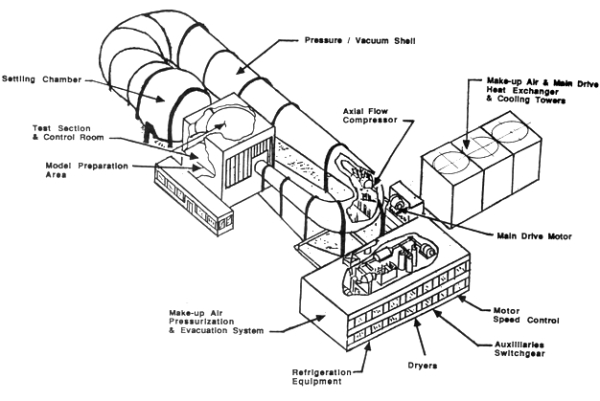
Figure 2 provides a plan view of the overall pressure shell geometry. The center-lines of the longitudinal sections are parallel and the horizontal centerline is parallel to the ground plane. The shell is fabricated from American Society for Testing Materials (ASTM) A516 grade 70 material, varying in thickness from 0.75 to 2.0 inches. Design and construction of the pressure shell is required to be in conformance with ASME code.6 All other applicable industry codes and standards are also imposed (e.g., American National Standards Institute, American Society for Testing Materials, American Institute of Steel Construction, American Welding Society, National Fire Protection Association, etc.).7,8
FIGURE 2: Typical Pressure Wind Tunnel Layout (plan view).
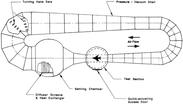
To accomplish proper air flow, multiple sets of turning vanes are positioned to aid the wind tunnel air in transitioning through the corners while a number of flow screens are located in the tunnel's settling chamber to straighten the air and attain laminar flow through the test section. Two isolation valves are provided to close off the ends of the test section plenum so that the major volume of the tunnel may remain pressurized while the spherical plenum is depressurized for access. The seals will be contained so if they should rupture, they will not injure personnel.5
Method of Analysis
Pressure vessels are commonly used structures throughout industry with well-defined design criteria, such as those provided by ASME.6,9 While the quick-actuating access door proposed for the pressure wind tunnel would be an off-the-shelf design, the NASA Ames System Safety Office wanted to ensure that a knowledgeable decision would be made about using this type of door in this unique application. Thus, it was necessary to collect failure data and information on hazard controls specific to this type of design.
How to obtain the necessary failure data specific to the quick-actuating door was not readily apparent. Rather than conducting an exhaustive literature search, it was more prudent to instead conduct an industry survey of failure data relevant to specific design parameters of interest. This section summarizes the stepwise procedures used to identify data requirements, the data sources ultimately utilized, and the rationale for these decisions.
Not all avenues explored proved to be fruitful and it was often necessary to follow an iterative approach until the proper parameters could be defined. A six step approach was used to systematically gather, correlate and analyze data.
Step 1. Tailor Data Collection Requirements
Step 2. Standardize the Nomenclature
Step 3. Differentiate Important Variables
Step 4. Define the Acceptable Level of Confidence
Step 5. Define the Data Collection Methodology
Step 6. Identify Appropriate Data Sources
In the following paragraphs, each of the steps is further defined and expanded to provide greater detail of the methods of data collection and reduction used.
Step 1: Tailor Data Collection Requirements
The first step was to generate a list of salient design parameters (including operational characteristics) that would (1) be used as a framework for systematic data collection and (2) support the analysis and testing of general hypotheses relating to accidents resulting from failure modes associated with the design failure data and any hazard controls were initially sought for comparable design parameters and operational characteristics of the quick-actuating door, listed below. Those marked with an asterisk (*) were attributes specifically identified in the failure data. Conversely, unmarked attributes are those not specifically identified in the data bases reviewed.
Salient Design Parameters
| *Dimensions (size) |
1.5 ft round door |
| Temperature |
+30 to +160oF (shell temperature) |
| Pressure |
15 psia (vacuum) to 103 psia |
| Cycling |
Approximately 10 cycles per day for 40 years (on the test section) |
| Seal type |
Flat gasket or 1/2" double O-ring |
| Material |
ASTM A516 gr 70 |
* Maintenance
Provisions |
Quality control to be used during fabrication plus daily, monthly, and annual nondestructive evaluation |
| Pressure-to-open |
Vessel internal pressure acts to unseat the door |
* ASME Code
Compliance (6) (9) |
Section VIII, Division 1 UG-35 Section VIII, Division 2 |
Step 2: Standardize the Nomenclature
In proper data collection, it is essential to determine the proper nomenclature so as to standardize and avoid the confounding of data. The key areas investigated and standardized are described below.
- Pressure Vessel: ASME Section VIII Division 1 U-1 definition was utilized for standardization.9
- Pressure: Greater than 15 psi and less than 3000 psi
- Volume: No minimum
- Size: Inside diameter or cross-section larger than 6 inches. No limit on length
- Quick-actuating
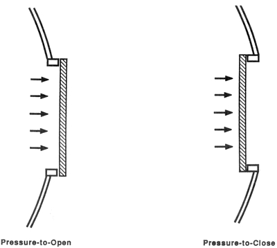
Quick-actuating doors or closures are used on certain types of unfired pressure vessels to facilitate loading or unloading of materials, or on vessels used to process products or goods under pressure and at an elevated temperature. Depending on the process, these vessels may be called autoclaves, sterilizers, vulcanizers, reactors, etc.10 For purposes of this analysis, quick-actuating doors were equated with breech lock or bayonet doors. Quick-actuating can be either pressure-to-open (or unseat) or pressure-to-close (or seat), as depicted in Figure 3.
FIGURE 3: Pressure-to-Open vs. Pressure-to-Close
- Accident/Incident/Injury/Death
While at NASA these terms are differentiated by the degree of the mishap, they were found to be used interchangeably by various data sources reviewed. Accidents include both death/injury and equipment loss/damage, but it was possible to separate out fatalities.
Step 3. Differentiate Important Variables
Because of what was learned in Step 2, it was evident that pressure-to-open was not differentiated from pressure-to-close in the data reviewed. Therefore, an effort was made to identify failure modes common to the open/close designs so that these could be studied separately from those failure modes unique to the pressure-to-open design. Figure 4 is an excerpt from the common failure modes identified.
Figure 4: Common Failure Modes: Pressure-to-Open and Pressure-to-Close
| Failure Mode |
Cause |
Effect |
Controls/Levels of Redundancy |
| I. Seal Failure |
Wear due to inadequate maint., abuse, etc. |
Scuffing, abrasion of seals lead to sudden seal failure and loss of pressure. |
1. Double Seal |
| II. Structural Failure due to Materials |
1. Inadequate Inspection
2. Fatigue Damage leading
3. Overstressing/Abuse of Door causes damage to door/vessel materials
|
Rapid propagation of a crack, to vessel destruction, massive property damage and multiple deaths. |
1. Adequate controls on door, vessel construction, inspection to prevent use of improper materials during construction.
2. Regular inspections/NDE to detect presence of cracks or crack-like defects which could propagate rapidly to failure.
3a. Vessel Pressure Control System Redundancies (TBD) minimize potential for overpressurization.
3b. Vessel/Door Abuse by personnel controlled by adequate design margins, procedures.
|
| III. Structural Failure due to Design |
Door/Vessel designed with inadequate design margins |
Door or vessel fails due yielding under applied stresses |
1. Adequate review/control of design process to ensure proper/adequate design margins are used for all possible loading/overloading conditions. |
| IV. Door Jams |
Due to tight tolerances and high pressures, door becomes jammed in vessel opening |
1. Loss of tunnel use, potential for major tunnel damage/repair to release jammed door while tunnel is depressurized
2. For Pressure to Open Doors, if personnel attempt to unjam door while system is still pressurized, if uncontrolled, door could suddenly swing open, resulting in severe injury or death to personnel, tunnel damage.
|
1. Door/vessel designs should be evaluated to determine potential for door jamming & possible design controls to prevent the doors from jamming or possible safety/warning devices to use should a door jam.
2. Use of interlocks on Pressure to Open Doors
|
Step 4. Define the Acceptable Level of Confidence
In order for NASA Ames to accept the risk associated with the quick-actuating door, a high degree of confidence that the data were statistically representative was desired. Thus, it was necessary to evaluate the overall safety of the design based on the total sample size of pressure vessels registered compared with reported failure data. Historical data was thought to be the most beneficial to this study rather than reliance on strict reliability predictions. Three main criteria were sought:
- Large sample size for statistical significance, i.e., number of comparable pressure vessels registered or in operation and large failure data bases
- Longitudinal data for at least 10 years in order to determine any trends, particularly toward risk reduction techniques
- No duplicate (or overlapping) registries or failure data bases to avoid confounding the data
Step 5. Define the Data Collection Methodology
The data collection methods selected for this study were simple and pragmatic. Simple data collection instruments were developed so as to systematically record findings for each of the variables identified in the preceding steps. It was decided that basic survey research methods such as telephone calls and correspondence with appropriate agencies would be the most effective for this study. It proved very important to establish files for data collection that would be used for later data reduction. Labeling and coding of detailed data are critical to this type of systematic data organization and retrieval.
Step 6. Identify Appropriate Data Sources
Identification of appropriate data sources was the next major challenge. While each organization or individual contacted had valuable information, it was evident that no single organization had all of the failure data centralized and often one organization was unfamiliar with the purpose of other industry organizations. Following is a list of data sources and commentary as to the relative usefulness of each for purposes of this study.
- ASME and The National Board of Boiler and Pressure Vessel Inspectors
Not surprisingly, these organizations provided the most useful data for this study. The Board provided registration, size, and accident statistics that proved to be vital to the analysis. These data were comprehensive and covered up to a 20-year span for certain criteria. There is, however, no way to determine the total number of pressure vessels in operation because those that are no longer in use are not necessarily reported as such. Thus, the total number is a cumulation of new registrations each year. The principal limitations in the Board's data (and all other data sources) are that the failure data are based only on what is reported, and pressure vessels cannot be differentiated by open/close types of design. It was a reported that an effort to better define these and data categories is included in the Board's long term planning. For example, "accident' information currently includes injuries and deaths, but also relatively minor incidents such as leaks.
- Occupational Safety and Health Administration (OSHA)
Both the state and federal OSHA agencies were contacted about failure data on pressure-to-open doors. Their data did not differentiate between these open/close types of quick-actuating doors. OSHA records accidents that meet specific criteria: more than five people hospitalized or one fatality. OSHA was able to provide summaries of actual pressure vessel accidents by using a key-word abstract database that includes data starting from 1984. The state, or CAL OSHA, does not certify pressure vessels but it does not administer ASME code in California.
- Insurers
The major industry insurers were contacted. All companies required that insured pressure vessels be designed to ASME code. Additionally, it was learned that insurance is not based on failure or accident rates, as is car insurance, but on the potential damage to the pressure vessel site. Thus, a pressure vessel in a highly populated and strategic technical center, such as NASA Ames, would require maximum coverage compared with a pressure vessel in a remote area. To reduce their liability, insurers require inspections after manufacture and during periodic maintenance. However, these inspection criteria are proprietary. While failure data are derived from actual accidents, pressure vessels are not always broken out separately from other types of equipment. Thus, the data are not consistently recorded. For the most accurate non-proprietary failure data, all insurers recommended contacting ASME and The National Board of Boiler and Pressure Vessel Inspectors.
Insurance companies contacted included:
- Hartford Steam Boiler -- This is the largest insurer of pressure vessels, but their data are kept proprietary.
- Industrial Risk Insurers -- This company was able to provide some general company failure data as well as general inspection criteria required of the insured.
- Factory Mutual System Companies -- This company reported the largest loss data base in the world, but their data are also proprietary and pressure vessels are not their principal market. It was reported that this company is presently developing the capability to sort data by key attributes such as pressure vessel age, type, and contributing failure cause. The Standards Division at Factory Mutual derives its standards from actual accidents.
- Technical experts
Several individuals and companies were contacted who were knowledgeable about quick-actuating door designs. They, in turn, recommended contacting ASME and The National Board of Boiler and Pressure Vessel Inspectors. Among those contacted was Sandia National Laboratories in New Mexico. This is noteworthy because Sandia is currently conducting a study on pressure vessels tested to failure. The purpose of this study is to develop analytic methods of predicting failures in certain systems, beginning with a pressure-to-open design using light water reactors.11
- Autoclave manufacturers
Several of those listed in the Thomas Register were contacted to determine if they had failure data on their designs.12 Typically they did not. However, specific companies, such as Thermal Equipment Corporation in California, provided recommended maintenance schedules and criteria.13
- American Petroleum Industry (API)
API inWashington, D.C., does not register pressure vessels or keep failure data. API is a lobbying organization and a standards setting body. They write standards not covered elsewhere, such as by ASME.
- Pressure Vessel Manufacturers Association (PVMA)
This Illinois-based organization serves as a liaison with ASME and is a trade association representing manufacturers. ASME covers the design up to manufacturing and PVMA works from that point to ensure safe practices.
- Uniform Boiler and Pressure Vessel Laws Society
The purpose of this organization in New York is to lobby for adoption of ASME pressure vessel standards and to monitor which states have laws invoking ASME code. No failure data are maintained by this organization.
- Electric Power Research Institute
This organization in California has an extensive library of research projects and published reports, but no failure data base.
Results
Based on the parameters identified in the Methodology section and the resultant data collected, the following results are summarized, beginning with general findings and concluding with quantitative results. The information is arranged in logical sequence and not in the order collected or in order of importance.
General Findings
No Centralized/Comprehensive Data Base
No one agency or organization maintains a comprehensive or centralized failure data base. This is true in part because different organizations collect and utilize failure data for different purposes. Further, while insurance companies may have the world's largest loss data base, these data are proprietary and not available for study. The National Board of Boiler and Pressure Vessel Inspectors maintains the most comprehensive data base available to the public. Even with any shortcomings, it was the general consensus of those interviewed that the methods of pressure vessel registration, monitoring, and failure analysis used in the United States should serve as a model to the world.
Failures Associated with Quick-Actuating Doors
Three principal failure modes were associated with quick-actuating doors:
- Depressurization
Depressurization, or opening a door with pressure, is the most dangerous problem associated with quick-actuating pressure-to-open doors. However, the majority of all pressure vessel failures (80 percent) were found to be of the nonviolent type (leaks, etc.)
- Overpressurization
Due to material failure, the door can be blown off either a pressure-to-open or close design in an overpressurized condition.
- Human Error
Human error during installation, operation and maintenance accounted for the majority (90 percent) of the accidents and failures over the past 18 years.
Compliance with ASME code
While perhaps obvious, the need to design pressure vessels to ASME code was consistently recommended by all data sources reviewed, noting that UG-35 provides only general design criteria for quick-actuating closures.6,9 In the case of insurance companies, compliance with the code is actually prerequisite to obtaining insurance. While the data are random, it appears that the number of accidents associated with pressure vessels designed to code is less than those not in compliance.
Use of Safety Devices
Safety devices such as interlocks were recommended to prevent opening a door in a pressurized condition. Also recommended were positive mechanical locking devices or a solenoid for releasing the pin. Use of visual and audible warning devices was recommended for indicating any residual pressure.
Need for Proper Installation and Maintenance
The need for proper pressure vessel installation and maintenance was emphasized in the literature reviewed and by the experts surveyed.
Effect of Pressure Vessel Size
While there is a perceived impact of large pressure vessels having more serious failures, small pressure vessels can be as deadly as large ones. There has been some increase in small pressure vessel registration because air compressor tanks in pneumatic nailers, found at local hardware stores, are also included.
Other Design Parameters
Not all parameters researched could be identified in the data bases. These included temperature and pressure ranges and cycling, material used, pressure vessel age, and seal type. However, it was noted that Sandia National Laboratories is investigating the differences between natural and synthetic seals, which may result in design considerations in the future.11
Confounded Nomenclature and Data
The term quick-actuating was found to have several synonyms and data were reported differently for each term. Also, the "accident" category included not only equipment-related failures, but death and injury data, which made numerical calculations difficult. It appears that the percentage of injuries and deaths associated with quick-actuating doors is small (less than 1 percent) compared to the total number of pressure vessel accidents.
Scope of Pressure Vessel Registration
The National Board of Boiler and Pressure Vessel Inspectors estimated that most large pressure vessels are registered. Because of interstate transportation of pressure vessels, even those originating in states where registration is not required ultimately become registered.
Quantitative Results
Sample Size
Longintudinal data were obtained for pressure vessels registered by size (20 years), accidents/injuries/fatalities (18 years), and quick-actuating doors (8 years). These data are summarized by Figures 5, 6, and 7.
Figure 5: Pressure Vessels Registered by Size
| Approximately 9,021,900 unfired pressure vessels have been registered in the United States in the past 20 years (1967-1987, all types and sizes) 14 |
| "A" Size Index (S<10) |
6,719,300 |
| "B" Size Index (10<S<36) |
1,589,600 |
| "C" Size Index (36<S<60) |
454,500 |
| "D" Size Index (60<S<100) |
105,300 |
| "E" Size Index (100<S) |
153,200 |
| Total = |
9,021,900 |
| S = Size Parameter = Diameter X Length (in square feet) |
Figure 6: Annual Accident Statistics
| Pressure Vessel Accident Statistics (18 years, 1971-1988)15 |
| Average Number of Accidents |
356/year |
| Average Number of Personnel Injuries |
92/year |
| Average Number of Personnel Fatalities |
18/year |
| Quick-Actuating Door Accident Statistics (8 years, 1971-1978)15 |
| Average Number of Accidents |
3.25/year |
| Average Number of Personnel Injuries |
2.25/year |
| Average Number of Personnel Fatalities |
0.50/year |
| The probability of a quick-actuating door accident is only 1/100 (1%) of the overall probability of any pressure vessel accident (3.25/356 per year) |
| The probability of an injury or fatality from a quick-actuating door accident is approximately 2.7 times greater than the probability of an injury or fatality associated with other pressure vessel components and practices. |
Figure 7: Failure Trends
| Failure Types15 |
Percentage |
| Violent Failures - Explosion, Rupture |
~20% |
| Non-violent Failures - Collapsed, Cracked, Leakage |
~80% |
| Total = |
100% |
| Failure Causes15 |
Percentage |
| Mechanical/Electrical Devices - Cut-off Switches, Pressure Controls |
~10% |
| Personnel Error - Faulty Design, Fabrication or Installation, Corrosion/Erosion, Operational Error, Poor Maintenance, Lack of Good Judgment |
~90% |
| Total = |
100% |
Pressure Vessel Registration
Approximately 150,000 comparably sized pressure vessels with a size parameter greater than 100 sq. ft. have been registered over the past 20 years, averaging 7,500 per year. There is no means of determining how many pressure vessels are still in operation, since those taken out of operation are not necessarily reported.14
Accident Statistics
An annual average of 356 accidents have been reported from 1971 to 1988. Fatalities have largely been associated with the shell pressure boundary failure and not failure of the door. A detailed analysis of the data showed that until 1984, there had been an average of 8.6 fatalities per year. For reasons unknown, 1984 to 1986 showed a dramatic increase in this average (65), bringing the 18 per year annual average number of fatalities to 18.2. During the last two years, there has been an overall trend toward fewer fatalities, bringing the two year average down to 10 per year. The three year 1984 to 1986 anomaly could not be accounted for.15
Failure Causes
For all types of pressure vessels, failure causes fell into two categories: mechanical/electrical, such as failure of pressure sensors, and personnel error, such as during operation or maintenance. Personnel error accounted for approximately 90 percent of the failures. Failure data specific to quick-actuating doors could not be differentiated in the data reviewed.15
Risk Associated with Quick-Actuating Doors
Analysis of the data above shows that the average annual quick-actuating door accidents (3.25 per year) is less than one percent of the average annual pressure vessel accidents per year (356 per year). Given an accident occurs, the probability of an injury or fatality resulting from a quick-actuating door is approximately 2.7 times greater than the probability of an injury or fatality associated with other pressure vessel components and practices (e.g., safety valve failure, construction code violation, etc.).
Summary & Conclusions
At the NASA Ames Research Center, an essential medium-sized pressure wind tunnel is undergoing restoration. As part of this restoration, a quick-actuating door has been incorporated into the redesigned test section in order to improve test model access and test productivity. Because failure of a pressure vessel door can be catastrophic, and because there is a common perception that quick-actuating doors present inherent risk, a survey of applicable industry data bases was systematically conducted to collect accident data and evaluate failure modes and risk reduction methods.
It was concluded that the data does not fully confirm or refute the assumption of increased risk associated with quick-actuating doors. The data indicate that less than one percent of all pressure vessel accidents are associated with quick-actuating doors. However, if a quick-actuating door accident occurs, there is a 2.7 times greater probability that the accident will result in an injury or fatality. Human error was found to be the major (90 percent) cause of overall pressure vessel accidents, while the primary cause of quick-actuating door accidents was identified as opening the door without full depressurization. Additionally, a number of other design and operational guidelines were discovered that should be used to control or minimize risk. These findings were then provided to NASA Ames engineers for comparison with the design and maintenance practices proposed for the test section quick-actuating access door, with the following results:
Compliance with Design Codes and Standards
The proposed test section access door design meets applicable codes and standards, including ASME Section VIII, Division 2.
Use of Safety Features
Safety devices will be incorporated to prevent or control potential hazards. These devices include mechanical stops, interlocks, and warning devices to prevent premature door opening.
Maintenance after Manufacture/Installation
The planned maintenance support activities are commensurate with or are more conservative than known requirements for maintenance intervals and acceptance criteria specified in current industry recommendations, such as those listed below.13,16,17,18
- Conservative maintenance and inspection schedules are planned
- Periodic nondestructive evaluation is scheduled
- Special procedures and personnel safety training for door operation are planned
Compliance with NASA Ames Safety Criterion
Based on the identified failure causes, accident statistics, and planned incorporation of all of the risk reduction measures listed above, it is believed that the proposed quick-actuating pressure vessel door design will not fail catastrophically during its 40 year life cycle.
Recommendations
As a result of this study, it is clear that severe pressure vessel accidents are a major public concern and the prevention of quick-actuating door failures warrants the closest attention. Thus, the following general recommendations for improving data collection and retrieval and for the advancement of pressure vessel design and technology are provided.
Standardize Data Collection/Nomenclature
A uniform set of standards and criteria should be developed so that pressure vessel data can be collected by different agencies and made available to designers. This would necessarily include nomenclature differentiating different types of pressure vessels, discrete categories of accident data, and detailed design/failure mechanisms. With this kind of standardization, comparative analyses could be readily performed on any desired design parameter.
Develop a Comprehensive Failure Data Base
While it might be desirable to design organizations to have access to a comprehensive data base, development of such a data base may not be feasible or beneficial for any one agency. However, this concept should be explored by service providers.
Ensure Effective Resource Utilization
In order to achieve needed improvements in pressure vessel design, all available data sources should be utilized. Insurance companies with large loss data bases should consider making their proprietary data available. Even though the potential for damage would remain, the knowledge of failure causes and resultant design solutions would ultimately serve to reduce the number of accidents.
Identify Needed Research Directions
Areas of pertinent research should be identified and funding encouraged. There is presently a dearth of experimental data to validate analytical models that predict pressure vessel failures. Sandia National Laboratories is conducting studies on containment of shell structures and pressure boundaries tested to failure. The results of these studies may have an impact on design considerations and safety precautions in the future.
Effective NASA/Industry Cooperation
Cooperation between NASA and industry has a long and successful history. Since the 1980s approximately 50 percent of the NASA workforce has been composed of industry contractors. In order to maintain its technological edge, NASA must utilize applied expertise gained within industry to perform its research and scientific studies. NASA then retums to industry new knowledge and scientific understanding so that industry may develop improved products and optimal designs.
For the current pressure wind tunnel restoration project, NASA AMES has call upon different experts in the pressure vessel community as resources in defining a safe and efficient design of the quick-actuating pressure vessel access door. The design research to be performed in this wind tunnel will extend into the twenty-first century and has the capability of yielding untold advancement in aeronautics. The pressure vessel commu- nity should be proud to have an integral part of this important evolution at NASA Ames.
Definitions
Catastrophic hazard.
A perilous condition that can result in either death or a permanent disabling injury and/or damage resulting in a cost of at least one million dollars.
Hypersonic.
A speed that is usually in excess of five times the local speed of sound. Mach 5 or greater.
Laminar flow.
A flow field in which all elements of the flow are traveling in a uniform and parallel direction. A non-turbulent flow field.19
Mach number.
A number representing the ratio of the speed of a body to the speed of sound in the surrounding atmosphere. A Mach number of 2 indicates a speed that is twice the speed of sound.
Pressure-to-close door.
A pressure vessel door design in which the vessel pressure acts to increase the compression on the door seal and to move the door towards the pressure vessel structure. Usually a pressure-to-close door will open into the pressure vessel chamber.
Pressure-to-open door.
A pressure vessel door design in which the vessel pressure acts to minimize the compression on the door seal and to move the door away from the pressure vessel structure. Usually a pressure-to-open door will open outward from the pressure vessel chamber.
Quick-actuating door.
A pressure vessel door design that allows for the rapid release of the force that holds the door shut. Usually these designs incorporate a bayonet or a breech lock fitting as opposed to a large number of threaded fasteners. A quick-actuating door can be either a "pressure-to-open" or a "pressure-to-close" design.
Reynolds number.
A dimensionless number representing the inertial and viscous forces in a flow. It is the ratio of the air (or fluid) velocity to the shear velocity. When performing scale model testing, it is imperative to maintain the Reynolds number of the test item consistent with the Reynolds number of the conditions modeled.
Sonic.
The speed of sound in air. Approximately 741 miles per hour at sea level. The speed of sound increases at higher elevations as the air density decreases.
Subsonic.
A speed that is less than the local speed of sound.
Supersonic.
A speed that is above the local speed of sound.
Transonic.
A speed range that goes from below to above the local speed of sound.
Acknowledgements
Support for the preparation and development of this paper was provided under a government support services contract to Boeing Aerospace Operations, Inc.
This paper is not the product of the authors only -- others were involved in providing ideas, insights, and technical guidance. At NASA Ames they were: Leonel S. Stollar, Chief of Safety, Reliability, and Quality Assurance, for his project leadership and technical support; Laura W. Doty, Chief of the Office of System Safety and designated System Safety Contracting Officer's Technical Representative, for her technical direction and insightful guidance throughout this effort; wind tunnel restoration project personnel Harry W. Gobler, Deputy Project Manager for Engineering, and John N. Perry and Robert W. Meneely for their expertise relied upon in understanding the wind tunnel test section design and in identifying data sources; Jason R. Brown, System Safety Engineer at Boeing Aerospace Operations, Inc.; lastly, the invaluable technical assistance provided by Anne R. Slayton, from the Information and Statistics Department of The National Board of Boiler and Pressure Vessel Inspectors, proved to be crucial in locating and interpreting the necessary longitudinal failure data. The authors thank all of them.
References
1 Factory Mutual System Companies, 1151 Boston Providence Turnpike, Norwood, Mass. 02062
2 Safety, Reliability, and Quality Assurance Provisions for the Office of Aeronautics, Exploration and Technology. NASA Handbook NHB 5300XX (Proposed). NASA Headquarters, Washington, D.C., 1989.
3 Health and Safety Manual. Chapter 5: Facility Operational Safety. AMES Handbook AHB 1700 1. NASA Ames Research Center, Moffett Field, CA., 1986.
4 Meneely, R W. History of Baseline Development of the Test Section Isolation System. NASA Ames Research Center, Moffett Field, CA.,1988.
5 Preliminary Engineering Report. Norman Engineering Co., NASA Ames Research Center, Moffett Field, CA., 1987.
6 ASME Boiler and Pressure Vessel Code, Section VIII, Division 2, Rules for Construction of Pressure Vessels, American Society of Mechanical Engineers, 1986 Edition.
7 Zimmer, D.A. Subsystem Hazard Analysis Report for the Pressure Wind Tunnel Restoration Project Sl, S2, S3 Shell Replacement. Boeing Aerospace Operations, Inc., NASA Ames Research Center, Moffett Field, CA., 1989
8 Management Plan for the Pressure Wind Tunnel Restoration Project. NASA Ames Research Center, Moffett Field, CA., 1987.
9 ASME Boiler and Pressure Vessel Code, Section VIII, Division 1, Rules for Construction of Pressure Vessels, American Society of Mechanical Engineers, 1986 Edition.
10 Snow, M.L. Jr. "Quick Actuating Closures." Bulletin. The National Board of Boiler and Pressure Vessel Inspectors Vol.43, No. 4, April 1986.
11 Sandia National Laboratories, Containment Technology Division, Albuquerque, New Mexico.
12 Thomas Register of American Manufacturers. Thomas Publishing Co. New York, 1989. (Vol. 1).
13 Recommended Maintenance Instructions for Autoclave Systems. Thennal Equipment Corporation, Torrence, CA., 1989.
14 Boiler and Pressure Registrations (1971-1987), Bulletin. The National Board of Boiler and Pressure Vessel Inspectors, Vol. 33, No. 4; Vol. 39, No. 2; Vol. 43, No. 2; Vol. 45, No. 2.
15 Incident/Accident Reports (1971-1988). Bulletin. The National Board of Boiler and Pressure Vessel Inspectors, Vols. 30-33, No. 1; Vols. 34-37, No. 2; Vol. 38, No. 1; Vol. 39, No. 2; Vols. 39-45, No. 4; Vol.45, No. 8, 1971-1988.
16 "Inspection of Quick-Actuating Closures." Bulletin. The National Board of Boiler and Pressure Vessel Inspectors,Vol. 45, No. 6,1988.
17 Whitley, B.L. "Quick Opening Closures." Bulletin. The National Board of Boiler and Pressure Vessel Inspectors, Vol. 37, No. 4,1980.
18 Perreira, D.C. "Insuring Safe Operation of Vessels with Quick Opening Closures." Bulletin. The National Board of Boiler and Pressure Vessel Inspectors, Vol. 37, No. 4,1980.
19 Eldredge, J.W. Laminar Flow. Boeing Aerospace Operations, Inc., NASA Ames Research Center, Moffett Field, CA. ,1988.
Editor's note: Some ASME Boiler and Pressure Vessel Code requirements may have changed because of advances in material technology and/or actual experience. The reader is cautioned to refer to the latest edition of the ASME Boiler and Pressure Vessel Code for current requirements.