Welding Symbols: A Useful System or Undecipherable Hieroglyphics?
Bill Green
Former National Board Consultant
Retired Professor Emeritus in Welding Engineering, The Ohio State University
Winter 1996 (Updated July 2013)
Category: Design/Fabrication
Summary: The following article is a part of National Board Classic Series and it was published in the National Board BULLETIN. (6 printed pages)
Welding symbols, when properly applied to drawings and, as importantly, when correctly interpreted, offer a potentially convenient way of controlling the welding of a particular joint.
The need for consistency in both the application of welding symbols to engineering drawings, and the accurate interpretation by personnel directly involved in manufacturing or construction, led to the development of a standard for these activities. The current American standard for welding symbols was originated by the American Welding Society and approved by the American National Standards Institute as ANSI/AWS A2.4:2012, Standard Symbols for Welding, Brazing and Nondestructive Examination.
Part A of this standard covers welding symbols, Part B deals with brazing symbols, and Part C describes symbols for specifying nondestructive examinations.
Welding Symbols
Although the basic symbol system is uniform, there is a need for some flexibility, as specific circumstances differ from one shop to another and field operations may involve entirely different situations. There are, therefore, often several ways to specify a given weld. Also, because cost is a consideration and is related to the specific equipment to be used, the details of joint geometry will vary from one manufacturer to another.
There is a considerable advantage to developing a shop standard for use with welding symbols. A shop standard for this purpose will establish the details that apply to all normal or standard joints. Welding symbols can therefore specify the welding without including all of the many possible details within the symbols. Simpler welding symbols are easier to add to a drawing and to interpret. Fewer errors are a benefit of this approach.
This article focuses on those welding symbols associated with typical applications with ASME Code items.
The Arrow
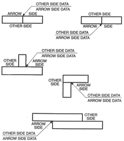
The first element of a welding symbol to consider is the arrow. The arrow is an essential part of every welding symbol and must point to the joint to be welded. The stem of the arrow should not be a horizontal line on the drawing. The side of the joint to which the arrow points is, by definition, the "arrow side" of the joint, and the opposite side of the joint is the "other side" of the joint (Figure 1).
FIGURE 1
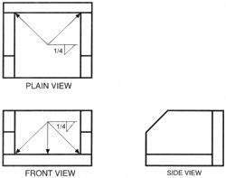
Often only limited space is available on a drawing for welding symbols. To minimize the number of welding symbols required, it is permissible to use more than one arrow in a single welding symbol if each joint to which an arrow is pointing is to be welded in exactly the same way. Since a welding symbol specifies welding of only the joint to which an arrow is pointing, and a change of direction or change in geometry constitutes the end of a joint, a multiple arrow welding symbol can be very helpful, particularly around closed corners (Figure 2).
FIGURE 2
The Reference Line
Another essential part of all welding symbols is the reference line, which is a straight line, drawn horizontally on a drawing, and connected to the arrow. The arrow may be connected to either end of the reference line (Figure 1).
Information relating to the "arrow side" of the joint is placed below the reference line and information relating to the "other side" of the joint is placed above the reference line. These positional relationships exist whether the arrow is attached to the left or right end of the reference line, and do not change as the angle between the arrow and the reference line varies (Figure 1).
The sequence of operations necessary to produce a specified weld is not indicated by the normal single-reference-line welding symbol. For example, if welding is to be done on both the "arrow" and "other" sides of a joint (typically called a double weld), a single-reference-line welding symbol does not specify which side of the joint is to be welded first. In fact, the symbol does not specify completion of the welding from one side prior to the start of the welding on the opposite side. These details are normally left to the personnel interpreting the welding symbol, with the requirements of the completed weld specified by the symbol.
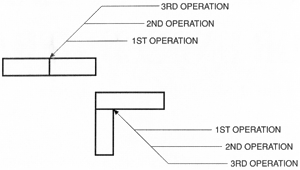
If the sequence of operations needs to be specified, a multiple-reference-line welding symbol may be used. Two or more reference lines may be connected to the same arrow, with the reference line closest to the arrow specifying the first operation, followed by the operations specified by the sequence of reference lines reading upward or downward from the arrow (Figure 3). It should be noted that operations other than welding, such as nondestructive examinations, can be specified by a multiple-reference-line symbol.
FIGURE 3
The Tail
A third element to be considered is the "tail" of the welding symbol. The tail is drawn as agreater-than (>) or less-than(<) symbol, connected at the end of the reference line opposite the arrow. Information for which there is no specific provision elsewhere in the symbol is placed to the left or right of the tail as appropriate.
Reference to the approved welding procedure specification (WPS) is an example of information appropriate in the tail of a welding symbol. Since a WPS can contain all of the details applicable to a specific joint, a welding symbol composed of an arrow, reference line, tail and applicable WPS designation would be sufficient to completely specify the welding of the joint.
The welding process to be used is often specified by entering process designation letters in the tail of the welding symbol. The American standard includes two lists of processes and their corresponding designation letters. Table 1 groups similar processes, such as arc welding, brazing, resistance welding, and thermal cutting, while Table 2 arranges the processes alphabetically.
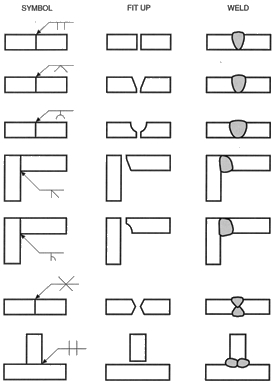
Groove Welds
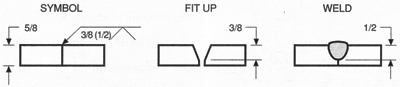
Additional information may be included in a welding symbol, even if also included in a WPS. For example, V-, U-, bevel-, or J-groove welds may be specified to provide increased weld size in a given joint, compared to that obtainable with a square-groove weld. The choice is usually made on the basis of cost for the completed weld. A groove-weld symbol may be added to a welding symbol, below the reference line, to specify a weld only on the "arrow side" of the joint (single weld); above the reference line, to specify a weld only on the "other side" of the joint (also a single weld); or weld symbols may be added both below and above the reference line, to specify a double weld (Figure 4).
FIGURE 4
Complete Joint Penetration
Since many applications require welds providing complete joint penetration (CJP), there are several ways to specify this condition. One way is to use an arrow, a reference line, and add CJP in the tail of the symbol. This symbol specifies complete joint penetration with no detail as to how the final condition is to be achieved. Such a symbol may be appropriate when there is uncertainty as to what specific equipment will be available when the work is to go through the shop. Later, when equipment availability is known, it is a good practice to submit assembly drawings to engineering for final approval, with welding symbols containing all pertinent details.
A second way to specify complete joint penetration is to include a single groove-weld symbol or double groove-weld symbols (must be the same weld symbol on both sides of the reference line), without any dimensions to indicate depth of bevel or weld size. It should be noted that partial joint penetration can be specified by adding the depth-of-bevel dimension and the required weld size (in parentheses) to the left of the groove-weld symbol or both symbols of a double weld (Figure 5).
FIGURE 5
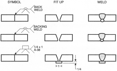
Inclusion of a backing weld symbol or back-weld-symbol, opposite a groove-weld symbol, specifies complete joint penetration if no depth-of-bevel or weld-size dimensions are added. Also, the inclusion of a backing symbol, opposite a groove-weld symbol, again without depth-of-bevel or weld-size dimensions, specifies complete joint penetration (Figure 6). Although there are provisions for specifying the root opening (gap), groove angle, and finish contours of welds, it is suggested that these details are best specified by a shop standard.
FIGURE 6
A discussion of groove welds should include at least mention of the scarf weld, a type of weld used on lighter gage material in small diameter piping, tube-to-tubesheet applications, and attachment of seats in smaller valves. This type of weld is intended for use with brazed joints, covered in Part B of the standard. There are two additional groove-weld types: the flare-bevel and the flare-V. These welds are used extensively in industries in which solid rounds, piping, and square and rectangular tubing are employed for structural purposes, rather than withstanding internal pressures typical of boilers and pressure vessels. The flare-type groove welds are therefore more common in the construction of buildings that house ASME Code items than in the manufacture of the items.
In a few cases there may be need to specify complete joint penetration plus a measurable reinforcement on the root side of a single-welded joint (welding from one side only). The addition of the "melt-through" symbol, on the opposite side of the reference line from a groove-weld symbol, identifies this requirement. The height of the root reinforcement may be specified by adding the appropriate dimension to the left of the melt-through symbol (Figure 7).
FIGURE 7
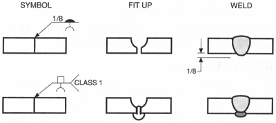
The use of consumable inserts has become more popular over the years, particularly in pipe joints, creating the need for a symbol to specify them. An open square, placed on the reference line opposite a groove-weld symbol, indicates the requirement for a consumable insert. The AWS consumable insert class must be added to the tail of the welding symbol, unless that information is specified in some other way (Figure 7).
Fillet Welds
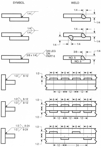
Fillet welds are used extensively in industries including those producing boilers and pressure vessels. The fillet weld symbol is a right triangle placed on the reference line with the perpendicular leg always on the left. The dimension specifying the leg size of a fillet weld is placed to the left of the fillet weld symbol, and on the same side of the reference line.
Since the load-carrying capacity per pound of fillet weld is greatest for equal-leg fillet welds, they are used unless some geometry restriction requires the use of unequal-leg fillet welds. In these few cases, both leg dimensions, separated by a multiplication sign, are placed to the left of the fillet weld symbol. The order of the leg dimensions is not significant and the orientation of the weld must therefore be shown on the drawing.
In contrast to groove-type welds, fillet welds do not always extend for the full length of the joint. The length of a fillet weld, which has a length less than the length of the joint, is specified by placing the required dimension to the right of the fillet weld symbol. If the exact location of such a weld is critical, dimension lines, hatching, or detailing is necessary. The omission of a length dimension, of course, specifies a fillet weld for the full length of the joint.
Also, in contrast to groove welds, fillet welds are often specified as intermittent welds, meaning they are not continuous welds. For an intermittent weld, the segment length dimension is placed to the right of the fillet weld symbol, followed by a hyphen and pitch dimension. The pitch is the distance between centers of segments on one side of the joint.
Intermittent fillet welds can be specified on both sides of a joint by placing a fillet weld symbol both below and above the reference line. Intermittent fillet welds with the segments directly opposite across the joint are called chain intermittent fillet welds. If the segments of intermittent fillet welds are to be staggered in a symmetrical manner on both sides of a joint, the sequence of fillet size, fillet weld symbol, segment-length dimension, multiplication sign and the pitch dimension are offset, left to right, on one side of the reference line (Figure 8).
FIGURE 8
There are also provisions in the American standard for specifying the contours of fillet welds and even the method by which the contours are to be produced. As with groove welds, these details are best controlled through a shop standard.
Non-North American Company Standards
Increased interaction between domestic and non-North American companies has led to more frequent interpretation of drawings away from their country of origin. Fortunately, the American standard has included metric dimensions along with U.S. customary units for many years, which should minimize any associated problems.
The ISO standard for welding symbols, though very similar to the American standard, has some differences. The biggest difference is the location of the arrowside and otherside information. The ISO Standard and AWS 2.4 are opposite. The AWS 2.4 Standard puts the arrowside information under the reference line and the ISO Standard puts it above the reference line. The ISO standard provides for the specification of a fillet weld size as either the leg dimension (as with the American standard) or the throat dimension. Since with equal-leg fillet welds, the throat dimension is approximately 70 percent of the leg dimension, it is essential that this potential difference be recognized. Also, the ISO standard locates the pitch dimension of intermittent welds in the same location specified by the American standard. However, the pitch dimension, by definition of the ISO standard, is the clear distance between segments rather than the distance between centers of segments.
Brazing Symbols
Brazing symbols are similar to those used to specify welds. An arrow, reference line, and tail are used in the same way they are used in welding symbols. Because of the resulting mechanical properties, square- and scarf-groove symbols are more appropriate than the other groove symbols. The root opening or gap is also much more emphasized in brazing symbols compared to symbols specifying fusion welds. The approved WPS may be referenced in the tail of the brazing symbol. Current industry practices rely more on detail drawings to specify brazing applications than the use of brazing symbols.
Nondestructive Examination Symbols
The arrow, reference line, and tail used to specify a nondestructive examination (NDE), appear exactly the same as those used to specify welds and have the same significance. The various examination methods have been assigned designation letters which are placed below, above or both below and above the reference line to specify, respectively, examination on the "arrow side," "other side" or both sides of the part. Combinations of examinations may be specified by adding additional designation letters with an additional sign separating the methods. In those cases where there is no arrow or other side significance, or there is no preference from which side the examination is made, the designation letters are centered on the reference line.
The approved NDE procedure may be referenced in the tail of the NDE symbol. There is a provision that allows the number of examinations to be specified, and the field-examination and examine-all-around symbols may also be used.
Summary
Space does not permit complete coverage of the entire American standard. For more information, readers are referred to the ANSI/AWS A2.4:2012, available from the American Welding Society, 550 NW LeJuene Road, Miami, FL 33126.
Editor's note: Some ASME Boiler and Pressure Vessel Code requirements may have changed because of advances in material technology and/or actual experience. The reader is cautioned to refer to the latest edition of the ASME Boiler and Pressure Vessel Code for current requirements.